In detail: do-it-yourself repair of the rear axle Niva 21213 from a real master for the site my.housecope.com.
Adjusting the front axle of the niva is one of the key operations that ensures comfortable and trouble-free travel on roads of any quality.
The need to adjust the elements of the front axle is assessed by the presence of noise and vibrations arising in various operating modes of the VAZ 21214. Thus, conditionally acoustic signs can be divided into two groups: • Registered constantly;
• Fixed when braking with internal combustion engine or acceleration.
By their nature, the sounds can resemble: • Howl (wear of the main pair); • Crunch, "trolleybus" hum (destruction or hauling of the liner bearings, loose nut of the drive shaft, axle shaft bearings, incorrect adjustment of the gears of the main gearbox); • Intermittent "scuffing" (differential bearing).
The complexity of diagnostics in this case lies in the abundance of extraneous noise emitted by other parts of the car.
To carry out adjustment work on the front axle, the manufacturer provides special pullers, mandrels and devices. However, due to their limited distribution and high cost, their presence is not necessary, although it is desirable to save time and accuracy of tuning. Since the main parts of the RPM correspond to similar elements of the REM, the correspondence of the technological clearances and the procedure for carrying out repair operations is traced.
The main stage is preceded by preparation, including: 1. Draining the oil from the RPM through the drain hole;
Read with this We put the stretcher on the field, detailed instructions
2. Disconnecting the propeller shaft with a key 13
| Video (click to play). |
3. Removing the right wheel drive.
4. Dismantling the lower ball joint on the left side.
5. Removal of suspension braces.
6. Removing the gearbox from the brackets on the right and left using the stop.
This is followed by disassembly of the gearbox, thorough cleaning of surfaces from dirt and grease, and troubleshooting of components.
To carry out the operation, the original device A.95690, mandrel A.70184 or an analogue made according to the drawing are used.
The seating plane of the crankcase is positioned so that it takes a horizontal position. Then an absolutely flat metal bar is installed on the bearing bed. The distance from the bar to the mandrel is measured by inserting the adjusting rings from the set in increments of 0.05 into the gap under the bar. The measured value (base of the crankcase) is consistent with the correction applied to the pinion. When reassembling the assembly, it is recommended that the standard spacer be discarded to prevent re-repair. Instead, a non-deformable steel sleeve with a length of 48 mm is suitable (with a margin, if necessary, shorten it).
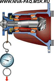
During turning, the parts control the force when turning the gear (should be 157-196 N · cm), for bearings with mileage, a torque of 39.2–58.8 N · cm is valid. The use of a proprietary dynamometer 02.7812.9501 is optional.
Acceptable accuracy will be ensured by a household balance wheel. When working with it, wind one end of a 1 m long cord around the flange, and fasten the other to the balance. Lock the torque by pulling the device in a perpendicular direction. So, new bearings should provide 7-9 kg, and with mileage - 2-3 kg.
With this read Repair and adjustment of the gearbox front and rear axles
The process involves replacing the support washers with new ones - thicker than before. A choice of 7 standard sizes with a step of 0.05 mm in the range of 1.8-2.1 mm. Washers material - bronze or steel. In this case, the gears are installed tightly, but with the ability to turn manually.
In accordance with the instructions, the lateral clearance and bearing preload are adjusted using the A.95688 / R tool.
In its absence, a vernier caliper of a suitable size will perform the given role.
To ensure the required preload, the distance relative to the bearing caps is recorded at the beginning of the tightening and at the end of it. The required difference between the values is 0.2 mm.
The side clearance is adjusted by bringing the driven gear to the leading one until it disappears. Initially, one of the nuts is in a free position, the other (working) is tightened. After eliminating the gap, gradually tighten the baited nut until the jaws of the caliper move apart by 0.1 mm. The backlash adjustment stops when a slight knock of the teeth appears. Then both nuts are evenly tightened to a distance of 0.2 mm. The correctness of the work performed is evidenced by a uniform backlash at any position of the gears.
The rear axle bearings, side clearance and the position of the contact patch in the meshing of the main pair are adjusted at the factory and, as a rule, do not require adjustment during operation. Their adjustment is necessary only after the axle bulkhead and replacement of parts, as well as when the bearings are heavily worn. The lateral clearance in the engagement of the main gear, which has increased due to wear of the teeth, is not reduced by adjustment, since this leads to a disruption of the engagement and, as a result, to increased noise of the rear axle or to breakage of the teeth. Backlash in tapered bearings is eliminated without disturbing the mutual position of the driven and driving gears.
Adjusting the drive pinion bearing preload
The need for bearing adjustment can be determined by the presence of axial play in the pinion gear. The axial play is measured with a disconnected propeller shaft using an indicator with a graduation value of not more than 0.01 mm while moving the flange in the axial direction. In this case, the indicator leg should rest against the flange end parallel to the pinion gear axis.
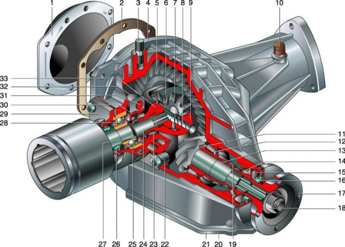
Rice. 5.32. Rear axle with a banjo beam with a separate gearbox (middle part): 1 - nut; 2 - drive gear flange; 3 - cuff; 4, 6, 11 - bearings; 5 - ring; 7 - an adjusting ring; 8 - gear case; 9 - driving gear; 10 - differential; 12 - semiaxis; 13 - gasket; 14 - lock plate; 15 - crankcase; 16 - differential bearing nut; 17 - differential bearing cover; 18 - oil filler plug; 19 - driven gear; 20 - breather
The adjustment must be carried out as follows:
- unpin and unscrew the nut 1, remove the flange 2, the oil seal 3 and the inner ring of the bearing 4;
- replace the adjusting ring 5 with a new one, the thickness of which should be less than the one being replaced by the value of the axial play plus an additional 0.05 mm when the vehicle has traveled less than 1000 km or 0.01 mm when the vehicle has traveled more than 10,000 km;
- put in place the inner bearing ring, a new oil seal, flange and tighten the nut to a torque of 160-200 N · m (16-20 kgf · m), then check the ease of rotation of the drive gear. If more effort is required to rotate the drive gear than it was before the adjustment, then it is necessary to replace the adjusting ring by increasing its thickness by 0.01-0.02 mm.
After completing the adjustment of the bearing preload, tighten the nut to a torque of 160-200 N · m (16-20 kgf · m) until the slot in the nut coincides with the hole for the cotter pin. The nut must only be tightened to match the hole for the cotter pin with the slot of the nut, since otherwise, due to insufficient tightening, the inner ring of the outer bearing may turn, wear the adjusting ring and, as a result, increase the axial play of the bearings. When tightening the flange nut, it is necessary to turn the drive gear to correctly install the rollers in the bearings.
After adjustment, it is necessary to check the heating of the bearings after the vehicle has been moving at a speed of 60–70 km / h for 20–30 minutes.In this case, the heating of the crankcase neck should not exceed 95 ° C (water that gets on the neck should not boil). Reduce the preload if it gets too hot.
Adjust the preload when replacing the bearings of the drive gear and the main gear in the following order:
- it is necessary to adjust the position of the drive gear by selecting the adjusting ring 7 (see Fig. 5.32), ensuring the size (109.5 ± 0.02) mm - the distance between the common axis of the side gears and the end of the drive gear adjacent to the adjusting ring 7;
- by selecting the adjusting ring 5, adjust the bearing preload of the drive gear. With correct adjustment, the torque of resistance to rotation of the drive gear should be in the range of 150-200 N · m (15-10 kgf · cm) for new bearings or 70-100 N · m (7-10 kgf · cm) for operating bearings. If the moment of resistance to rotation of the bearings is within the normal range, the nut must be pinned, otherwise the adjustment must be repeated. In this case, if the torque of resistance to rotation is less than the required one, it is necessary to reduce the thickness of the adjusting ring, and if it is more, it is necessary to select a ring of greater thickness.
After adjusting the preload of the bearings, it is necessary to install the differential assembly into the axle and adjust the preload of the differential bearings and the lateral clearance in the meshing of the final drive gears.
Adjustment of differential bearing preload and lateral clearance in the meshing of gears and final drive
Adjustment without bearing replacement.
To adjust the bearings, you must:
- remove the axle shafts, the crankcase cover and the cover gasket (for one-piece rear axle);
- remove the axle shafts and remove the gearbox from the axle housing (for the rear axle with a banjo beam);
Rice. 5.33. Checking the axial clearance in the differential bearings (banjo axle)
The rear axle of the car is made in the form of a hollow beam, to the ends of which flanges are welded with seats for the bearings of the axle shafts and holes for fastening the brake shields. In the middle, the main gear reducer with a differential is bolted to the beam, and from the side of the flanges, two axle shafts are inserted into the beam, transmitting torque from the reducer to the rear wheels.
The main gear is hypoid, its gears are matched for noise and contact, so they can only be replaced as an assembly (pair marking - 2106).
The main gear drive gear is made integral with the shaft (shank) and is installed in the neck of the gearbox on two tapered bearings. The outer rings of the bearings are pressed into the seats of the neck, and the inner ones are put on the shank. A spacer sleeve is installed between the inner rings; when the shank nut is tightened, the sleeve deforms, providing constant bearing preload. Bearing preload is controlled by the torque of the drive gear (other parts are not installed). For new bearings, the turning moment should be in the range of 157—197 Nm, for bearings after a run of 30 km or more - 39.2—59.0 Nm. In this case, the shank nut is tightened with a torque of 118-255 Nm, periodically checking the rotation of the drive gear. If the specified torque has already been reached and the tightening torque of the nut is less than 118 Nm, it is necessary to replace the spacer sleeve with a new one, as the old one is too deformed. Replacing the bushing is also necessary when the turning torque is higher than the allowable one (due to inattention when tightening).
If the main pair or the bearings of the pinion gear are replaced, it is necessary to re-select the thickness of the adjusting ring. It is mounted on the shaft between the pinion gear and the inner ring of the large bearing.
The final drive pinion is attached to the differential box flange with special bolts without washers. These bolts must not be replaced with any other bolts.The differential box rotates in two tapered bearings. Their preload, as well as the clearance between the teeth of the main drive gears, is regulated by nuts wrapped in split bearing beds. The half-axle gears are installed in the cylindrical seats of the differential box and rest on it through the support washers. These washers are selected in thickness so that the gap between the teeth of the satellites and half-axle gears is within 0 - 0.1 mm. The satellites are mounted on an axle with constant meshing with half-axle gears. On the axis there are spiral grooves for supplying lubricant to the rubbing surfaces.
The half-shaft at one end rests on a single-row ball bearing installed in the seat of the rear axle beam, and at the other (splined) end it enters the half-axle gear. The inner ring of the bearing is secured to the axle shaft by a snap ring fitted with an interference fit (shrink fit). The outer ring of the bearing is fixed by a plate, which, together with an oil deflector and a brake shield, is attached by four bolts and nuts to the rear axle beam.
1.3 liters of transmission oil are poured into the rear axle crankcase (practically - to the lower edge of the filler hole). The semi-axle outputs from the beam are sealed with oil seals. If the oil seals are leaking, the oil is directed through the oil deflector to the outside of the brake shield - so it does not fall on the brake pads. The stuffing box installed in the throat of the gearbox runs along the flange surface. An oil baffle is installed between the bearing and the flange. Oil leakage from under the self-locking flange nut (the same nut is used to adjust the bearing preload) indicates a loosening of its tightening. Operating the vehicle with a loose gear nut may result in damage.
To equalize the pressure outside and inside the rear axle housing, a breather is located on the rear axle beam above the gearbox. At every service check if the breather cap is stuck.
We check the tightness of all threaded connections and, if necessary, tighten them. The breather cap must be free of dirt and rotate freely. With our hands, we apply a force of about 10 kgf along the axis of the suspended wheel and determine the presence of a semi-axle backlash. It is allowed no more than 0.7 mm. The parking brake must be released during this check. Slight oil leakage (sweating) from under the front bearing of the main gear is allowed, but if the gearbox and the bottom of the car are heavily oiled above the main gear, the cuff should be replaced.
Determine the noise in the rear axle and, accordingly, the need for repairs can be based on the results of the following tests.
Test 1. We smoothly accelerate the car on a flat road from a speed of 20 to 90 km / h. At the same time, we listen to the noise and notice the speed at which it appears and disappears. We release the gas pedal and listen to the car in engine braking mode. Usually, noise comes and goes at the same speeds, both during acceleration and deceleration.
Test 2. We accelerate the car to a speed of 100 km / h, put the gear lever in neutral, turn off the ignition and roll freely to a stop. At the same time, we monitor the nature of the noise at various rates of deceleration.
In the first version, we tested the gearbox in the acceleration and deceleration modes under the load generated by the motor. In the second - without her. If the sound is present only during the first test, it may be caused by the gears of the reducer, the bearings of the drive gear or differential. If the noise appears in both cases, the source must be looked for elsewhere.
Test 3. Set the gear lever to neutral, start the engine and gradually increase the crankshaft speed. We compare the arising noises with those noticed earlier. If they are similar to the first test noise, this indicates that they are not coming from the gearbox.
Test 4. Noises detected in the first test and absent in subsequent tests are caused by the gearbox. To confirm, raise the rear wheels, start the engine and engage the fourth gear. We make sure that the noise really comes from the gearbox, and not from other components or parts.
We remove the gearbox to replace it, repair or replace the rear axle beam.
We hang out the rear axle.
We drain the oil from the rear axle housing (see here).
Disconnect the rear propeller shaft from the rear axle reducer flange (see here).
Holding the gearbox housing, use the "12" head to unscrew the eight bolts of its attachment to the rear axle beam.
... and a gasket.
Install the gearbox in reverse order.
Before installing the gearbox, we clean the mating plane of the beam. Install a new gasket. Before tightening the bolts securing the gearbox to the rear axle beam, apply sealant to the bolt threads.
Before removing, we clean the gearbox from dirt. We install the dismantled gearbox on the workbench.
Using the "10" wrench, unscrew the bolt securing the locking plate of the adjusting nut of the right bearing of the differential box ...
Similarly, remove the retaining plate of the left bearing adjusting nut.
Using a punch, we mark the location of the differential box bearing caps on the gearbox housing.
With a spanner wrench "17" we unscrew the two bolts securing the cover of the right bearing of the differential box ...
Remove the right bearing cover.
We take out the adjusting nut ...
... and remove the outer bearing race of the differential box.
Likewise, remove the cover, take out the adjusting nut and remove the outer ring of the left bearing of the differential box.
If we do not change the bearings of the differential box, then we mark their outer rings in order not to confuse them during assembly.
We remove the differential box assembly with the driven gear of the main drive, inner rings, cages and bearing rollers.
We take out the drive gear assembly from the gearbox housing with an adjusting ring, an inner ring, a cage and rear bearing rollers and a spacer sleeve.
Striking blows with a hammer through a drift on the inner ring of the rear gearbox bearing, ...
… Remove the inner ring with cage and rollers.
Remove the drive gear adjusting ring.
We remove the oil seal from the housing of the gearbox (see here).
... and the inner ring of the front bearing with cage and rollers.
With a punch we knock out the outer ring of the front bearing of the drive gear ...
Turning the crankcase over, knock out the outer ring of the rear bearing of the drive gear in the same way.
For disassembling the differential…
... with a puller we press the inner ring of the differential box bearing.
In the absence of a puller, insert a chisel between the end of the bearing inner ring and the differential box.
By striking the chisel, we move the inner ring of the bearing.
We insert two powerful screwdrivers (or mounting blades) into the resulting gap and press it ...
… Inner ring with cage and rollers.
Similarly, we press the inner ring of the other bearing.
Clamping the differential box in a vice with soft metal jaw pads, ...
… With a 17 ”spanner wrench, unscrew the eight bolts securing the driven gear to the differential box.
Using a hammer with a plastic striker, we knock down the driven gear from the differential box ...
Turning the satellites, take them out of the differential box.
We take out the side gears.
Before assembly, we wash the gearbox parts in kerosene and inspect them. We check the condition of the teeth of the main gears. Damage to at least one tooth (chipping, scuffing of the working surface) is unacceptable. With a fine-grained sandpaper, we eliminate minor damage to the pinion axle, the axle pinion journals and their mounting holes in the differential box.In case of serious damage to the parts, we replace them with new ones. If even minor damage to the surfaces of the bearing washers of the semi-axle gears is found, we replace the washers with new ones (with a selection of the thickness of the washers). Bearings of the pinion gear and differential boxes must be free of wear, with smooth working surfaces. Poor bearing condition causes noise and seized gear teeth.
The inner rings of the differential box bearings with cages and rollers are pressed onto the box with a suitable piece of pipe. We fix the driven gear on the differential box.
When assembling the differential, we lubricate the semi-axle gears with support washers and satellites with transmission oil and install them in the differential box. We turn the satellites and the gears of the semi-axles so as to align the axis of rotation of the satellites with the axis of the holes in the differential box, and insert the axis of the satellites. The axial clearance of each half-shaft gear must not exceed 0.1 mm. With an increased clearance, we replace the bearing washers of the semiaxis gears with new ones - of greater thickness. The moment of resistance to the rotation of the differential gears should not exceed 14.7 N.m (1.5 kgf.m) - the gears are turned by hand.
We check the ease of rotation of the differential gears.
Press the outer ring of the front bearing into the housing with a tool head of a suitable diameter (a piece of pipe).
Similarly, we press in the outer ring of the rear bearing.
The correct position of the drive gear relative to the driven gear is ensured by the selection of the thickness of the adjusting ring installed between the end face of the drive gear and the inner ring of the rear bearing. When replacing the main pair of the gearbox or the bearings of the drive gear, we select the adjusting ring. To do this, we make a device from an old drive gear: we weld a plate 80 mm long to the gear and grind the plate to a size of 50–0.02 mm relative to the end of the gear (the adjoining plane of the adjusting ring).
A device made from an old pinion gear.
We grind (or process with fine sandpaper) the place where the rear bearing is installed on the drive gear so that the inner ring of the bearing is installed on a sliding fit. On the manufactured device, we install the inner ring of the rear bearing with a cage and rollers and insert the device into the crankcase. Then we install the inner ring of the front bearing with a cage and rollers and the flange of the drive gear. Turning the gear wheel for the correct installation of the bearing rollers by the flange, tighten the flange mounting nut to a torque of 7.9–9.8 Nm (0.8–1.0 kgf.m).
We fix the crankcase on the workbench so that its attachment plane is horizontal. We install a curved ruler in the bearing bed with an edge so that the bed ruler touches along the line.
Using a set of flat probes, we determine the size of the gap between the ruler and the fixture plate.
The thickness of the adjusting ring is determined by the difference between the gap and the deviation from the nominal position of the new gear (taking into account the sign of the deviation).
The marking of the deviation from the nominal position (in hundredths of a millimeter with "plus" or "minus" signs) is applied to the tapered part of the gear shank.
For example, the measured clearance is 2.90 mm and the gear has a -15 deviation from the nominal position. We translate the deviation into millimeters: –15 x 0.01 = –0.15.
The required shim thickness is: 2.90 - (- 0.15) = 3.05 mm.
We install the adjusting ring of the required thickness on the new drive gear. We remove the device from the gearbox housing and remove the inner rings of the front and rear bearings with cages and rollers.
With a suitable piece of pipe, press the inner ring of the rear bearing with a cage and rollers onto the new drive gear.
We insert the drive gear into the gearbox housing.Install a new spacer sleeve, an inner ring of the front bearing with a cage and rollers, and an oil deflector. Having lubricated the working edge of the new oil seal with Litol-24 grease, we press it into the crankcase socket. Install the pinion flange.
Having locked the flange, gradually tighten the nut of its fastening with a torque wrench to a moment of 118 Nm (12 kgfm).
The preload of the drive pinion bearings is controlled with a dynamometer.
… Periodically checking the bearing resistance torque to the rotation of the drive gear.
If the moment of resistance to rotation turned out to be less than 157 Ncm (16 kgf.cm) - for new bearings, and for bearings after 30 km of run - less than 39.2 Ncm (4 kgf.cm), then tighten the flange mounting nut, do not exceeding the tightening torque. After that, we again check the moment of resistance to the rotation of the drive gear.
If the moment of resistance turned out to be more than 197 Ncm (20 kgf.cm) - for new bearings, and for worn-in bearings - more than 59.0 Ncm (6 kgf.cm), then the preload of the bearings is exceeded.
In this case, replace the overly deformed spacer with a new one and reassemble and re-adjust.
We install the differential assembly with bearings and adjusting nuts in the gearbox housing so that they come into contact with the outer rings of the bearings. We tighten the bearing cap bolts to the required torque.
We make a special wrench for tightening the adjusting nuts from a steel plate 49.5 mm wide and 3-4 mm thick.
The adjustment of the lateral clearance in the meshing of the main drive gears and the preload of the differential box bearings are carried out simultaneously, in several stages.
Using a vernier caliper, we measure the distance between the bearing caps.
We wrap the left adjusting nut (from the side of the driven gear) until the gap in the meshing of the main gears is completely eliminated.
We turn the right nut until it stops and tighten it by 1–2 teeth of the nut.
Tightening the left nut, we set the required lateral clearance of 0.08–0.13 mm in the meshing of the main gears.
With this gap, shaking the driven gear, with the fingers of our hand we feel the minimum backlash in the engagement of the gears, accompanied by a slight knock of the tooth against the tooth.
When the nuts are tightened, the bearing caps of the differential boxes diverge and the distance between them increases.
To set the preload of the differential box bearings, successively and evenly tighten both bearing adjusting nuts until the distance between the covers is 0.15–0.20 mm. Having established the preload of the bearings, we finally check the lateral clearance in the meshing of the main gears, which should not change. For this,…
... while slowly turning the driven gear three turns, use your fingers to control the backlash in the engagement of each pair of teeth.
If the clearance in the engagement turns out to be greater than the required one (0.08-0.13 mm), then by rotating the adjusting nuts we bring the driven gear closer to the driving gear or move it back if the clearance is less. In order to maintain the established bearing preload, we move the driven gear by tightening one of the adjusting nuts and loosening the other by the same angle.
After adjustment, install the locking plates of the adjusting nuts and fasten them with bolts.
The message in the conference "VAZ-classic" 02.11.06 (original), copied with the permission of the author.
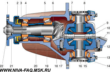
By the way, the first sign of the axial play of the drive gear is the appearance of oil on the throat of the gearbox.When the vehicle is moving forward, the gear loads the rear bearing and relieves the front bearing, trying to “wriggle out” from the engagement. In this case, in addition to the axial play, a radial appears in the front bearing and the oil seal on the flange 1 no longer retains oil.
If you often have to drive the car in reverse, and even under load, uphill - the agony of the “sick” unit will not last long. The fact is that in the reverse mode the drive gear, choosing the axial play, is screwed into the driven gear, as it were, shifting backward, which, with the conical shape of the gear rims, causes a huge lateral force in the bearings. In especially advanced cases, the backlash progresses like an avalanche and the gear "goes" back so far that it mills a deep furrow on the surface of the differential box. Of course, the cemented layer on the working surfaces of the teeth will be worn out by that time, the tops of the teeth are rounded and the hum of the rear axle will turn into a growl with an eerie crunch ...
How can you determine the suitability of certain parts for reuse in a newly assembled gearbox? The main couple, perhaps, will still serve - the final verdict will make her a noise test. Do not be alarmed: instead of an expensive stand with an electric drive, a conventional knob with a 24 ”head from a large set of socket tools will do, and the measuring acoustic complex will replace your own ears. The assembled gearbox (without a spacer sleeve, oil seal, oil deflector, differential parts and stoppers, but with an adjusted gap in the engagement of the pair) is fixed in a vice, placing cardboard under the jaws so as not to jam the flange. Then quickly rotate the drive gear by the flange nut. If, instead of a soft rustle of bearings, you hear a rumble resonating into the workbench cover, even more so a pulsating one - we throw out the main pair without a shadow of a doubt - no adjustment "by the contact patch" will save it.
You can also reject the main pair visually, for example, if the tape of the top of the drive gear tooth is not uniform in width, as in the new one, but is narrowed in the middle part. The edges between the tops and working surfaces of the driven gear teeth must be sharp, like a turning tool. If you see the slightest nicks or roundings, throw away the steam without hesitation. And, of course, the main pair must be replaced if chipping of the cemented layer, waves, risks and other defects are visible on at least one of the teeth.
The differential box must be replaced if its journals are squashed and the new bearings are easy to put on by hand. It is unacceptable to grind the necks under the repair bushings - they are already thin. Whenever the gearbox is repaired, the bearings should be replaced with new ones, even if the old ones look quite functional. The saturation of oil with metal wear particles does not pass without leaving a trace for them, so the savings are more expensive here.
There is no need for expensive, heavy-duty jaw pullers to press out the bearing rings - they are superbly replaced by two hardened, thin-tongued mounting blades - much faster than fitting a fixture. In addition, when pressing the bearing rings into the crankcase or onto the gear with a puller, the following drawback appears: tightening its screw to failure, you will not feel the full fit of the ring around the entire circumference without a gap. It is possible that when the unit is in operation, it will settle down a little more, loosening the bearing preload. In my experience, it is safer to press in rings with a hammer using mild steel pipe pieces as mandrels. The first blows will be "sticky" - the ring moves along the neck or in the bore, and then the hand will feel the sharp return of the hammer - that means that everything is "gap - zero". A few more light, “stroking” strokes around the circumference and you can be sure - the ring is set all the way.
To match it with the new main pair, we subtract from it the amount of the correction applied with an electrographic pencil in the middle part of the drive gear.The marking, made in sloppy, sweeping handwriting, includes four digits of the main pair number (it is also stamped on the driven gear) and one or two correction digits with a "+" or "-" sign, denoting hundredths of a millimeter. For example, the base of the crankcase is 2.65 mm, and the correction is "-7". Subtract: 2.65 - (–0.07) = 2.65 + 0.07 = 2.72. This means that a ring 2.70 or 2.75 mm thick must be placed under the rear bearing of the drive gear. If you don't have this, you can grind a thicker one, for example, in a lathe or, at worst, rubbing it on a plane with sandpaper.
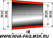
ATTENTION! In the picture, the length of the spacer sleeve is incorrect - it should be 48, not 44! (ALER: Corrected the number 4 to 8).
Having picked up the length of the sleeve, we disassemble the assembly again, rinse the parts and inspect them carefully. During the final assembly, be sure to install a new oil seal 2 (see Fig. Below) and, as a rule, oil slinger 3 is old, squeezed out unsuitable. There should be no groove on the flange 1 due to the work of the stuffing box. We degrease the thread of the gear with a solvent and lubricate it with reliable glue (epoxy, polyester, "Moment", etc.). The flange nut 27 (necessarily new - the one that was repeatedly tightened during adjustment is not suitable) we tighten "from the heart" - the thread withstands 30 kgf.m with a large margin. Now that all the parts on the pinion are pulled together by a force of 60 tons into a rigid, “monolithic” block, you can be sure that the bearing preload will be normal for many years. The glued nut will not turn away, loosen and loosen, as in the standard version, nothing can here anymore.
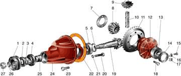
When assembling the unit, it is usually required to install new support washers 7 - thicker than the "native" ones.The half-axle gears must fit tightly into the differential, but turn by hand - this is what provides the Zhiguli bridges with silent and smooth, jerky-free operation (which has always caused the envy of Muscovites' owners). In total, there are seven standard sizes of support washers with a thickness of 1.8 to 2.1 mm (every 0.05 mm), and for any gearbox, both bronze ("classic") and steel ("Nivovskie") are equally suitable. If there are no washers of the required thickness, they are easy to make on a lathe - the part is primitive.
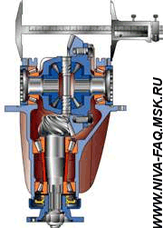
It is possible to adjust the side clearance in the main pair and the preload of the differential bearings without the monstrous device with two indicators (A.95688 / R) mentioned in the instructions. All this cumbersome equipment will completely replace a large caliper (see fig.). We measure the distance between the bearing caps before tightening the nuts and after. The difference should be 0.2 mm - this provides the required preload. To simultaneously adjust the lateral clearance in the gears, usually proceed as follows. By rotating one of the nuts 14 (the other is only baited), the driven gear is brought to the leading gear until the engagement gap is completely eliminated. Then the nut is screwed in until it stops and tightened by 1–2 teeth, while the vernier caliper shows an increase in the distance between the bearing caps by about 0.1 mm. Now we check the side clearance, and without any indicator. The required 0.08–0.13 mm is nothing more than the minimum perceptible play in engagement with the fingers, accompanied by a slight knock of the tooth against the tooth. It is enough to barely move the gears from the backlash-free position for it to appear. Additionally tightening both nuts 14, we achieve the divergence of the bearing caps to 0.2 mm while maintaining the required clearance in the main pair.
Before installing lock plates 16 and 17, slowly turn the driven gear three turns, probing for play in engagement on each tooth. If it is minimal and uniform for any position of the gears, consider that the gearbox is ideally adjusted. If the gap disappears in some sector of the teeth, causing the main pair to rotate tightly, the unit must be disassembled again. The runout of the differential box 12 can be easily eliminated in a lathe by milling the mating plane under the driven gear. Or you can just put in a new box. Some "experts" sometimes allow the installation of a "curve" of the differential box, adjusting the side clearance in the tightest position. But since our today's conversation is devoted to the individual and high-quality assembly of the gearbox "for yourself", such recommendations are unacceptable here.
So, the "piece-made" gearbox is ready to serve you until the machine is decommissioned. But before putting it back in place, make sure that the rear axle beam is not bent. This often happens after driving with an overload, and the misalignment of the axle shafts quickly destroys their splined connection with the differential gears. To check it, it is not at all necessary to have a huge surface plate, flanges, prisms, etc., listed in the instructions. It is enough just to look through an empty beam - all four holes for the axle shafts (two in the flanges and two near the gearbox cavity) should be located strictly on the same line, and the slightest curvature is immediately noticeable to the eye. In this case, the beam will have to be replaced.
It is by this technique that I sort out the REMs.
Update as of 08/01/12, author of Scout-22.
I am attaching a couple of files so that you can bring the finished drawings to the turner.
| Video (click to play). |
The first picture is a preview, click to open the file in full size in a new window:

