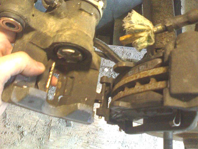
In detail: do-it-yourself repair of the rear caliper ford focus 2 from a real master for the site my.housecope.com.
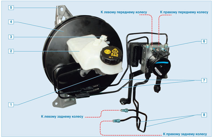
Brake system:
1 - the main brake cylinder;
2 - hydraulic drive reservoir;
3 - brake fluid level sensor;
4 - vacuum amplifier;
5 - pedal assembly bracket;
6 - ABS block;
7 - tubes of the main brake cylinder;
8 - tubes of brake mechanisms of rear wheels
The service brake system is hydraulic, double-circuit, with diagonal division of the circuits. One of the circuits of the service brake system provides the operation of the brakes of the left front and right rear wheels, and the other - of the right front and left rear wheels.
In normal mode, when the system is healthy, both circuits work. In the event of failure (depressurization) of one of the circuits, the other circuit provides braking of the car, albeit with less efficiency. The service brake system includes the wheel brakes, pedal assembly, vacuum booster, brake master cylinder, hydraulic reservoir, anti-lock braking system, as well as connecting pipes and hoses.
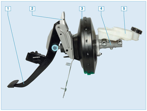
Pedal assembly with vacuum booster and master brake cylinder:
1 - brake pedal;
2 - pedal assembly bracket;
3 - vacuum amplifier;
4 - the main brake cylinder;
5 - hydraulic drive tank
The brake pedal is of the suspended type. A brake signal switch is installed in the pedal assembly bracket - its contacts close when the brake pedal is pressed, as well as a switch that issues a signal to the electronic control unit that the brake pedal is pressed. The vacuum brake booster is designed to reduce the force that must be applied to the brake pedal when braking the car by using a vacuum in the intake manifold of a running engine. The booster is located between the brake pedal and the brake master cylinder and is secured with four nuts to the pedal bracket. The vacuum amplifier is non-separable; if it fails, it is replaced with a new one.
| Video (click to play). |
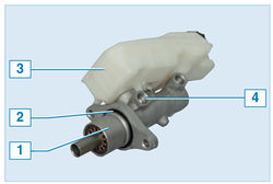
Brake master cylinder with reservoir:
1 - the main brake cylinder;
2 - a sealing ring;
3 - hydraulic drive reservoir;
4 - the screw securing the reservoir to the master brake cylinder
The brake master cylinder is attached to the booster housing with two nuts. On top of the cylinder there is a common reservoir for the hydraulic drive of the brake system and clutch, in which there is a supply of fluid. On the body of the tank there are marks of the maximum and minimum liquid levels. A liquid level sensor is installed in the reservoir, which, when the liquid level drops below the MIN mark, turns on the warning lamp in the instrument cluster. The sensor is a reed switch, the contacts of which are closed under the action of a magnet in a float located in the tank. When the liquid level drops, the float is lowered, and the approach of the magnet closes the contacts.
When the brake pedal is pressed, the master cylinder pistons move, creating pressure in the hydraulic drive, which is supplied through pipes and hoses to the working cylinders of the wheel brake mechanisms.
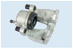
Front brake caliper
The front wheel brake mechanism is a disc, with a floating caliper, which includes a single-piston wheel cylinder.
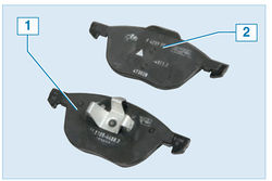
Front brake pads:
1 - inner block;
2 - external block
The brake pads of the front and rear wheels differ in design. The inner pads of the front brakes have spring clips for installation in the piston of the brake cylinder.
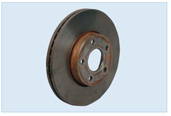
The front brake disc is ventilated for better cooling. The brake pad guide is attached to the steering knuckle, and the caliper is attached with two bolts to the guide pins installed in the shoe guide holes.Protective plastic covers are installed on the fingers. When braking, the pressure of the fluid in the hydraulic drive of the brake mechanism increases and the piston, moving out of the wheel cylinder, made integral with the caliper, presses the inner brake pad against the disc. Then the caliper (due to the movement of the guide pins in the holes of the shoe guide) is shifted relative to the disc, pressing the outer brake pad against it. A piston with a rubber sealing ring is installed in the cylinder body. Due to the elasticity of this ring, a constant optimum clearance is maintained between the disc and the brake pads.
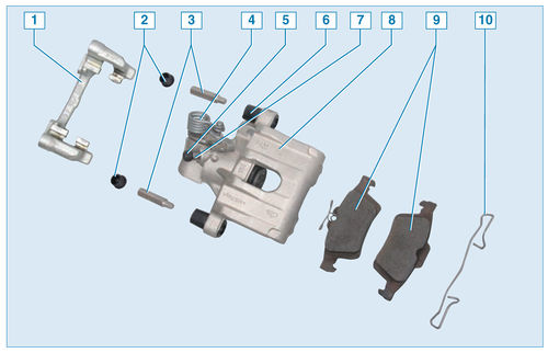
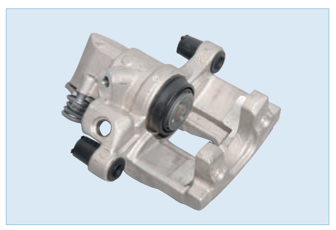
Rear wheel brake:
1 - shoe guide;
2 - protective covers for guide pin bushings;
3 - guide fingers;
4 - return spring of the parking brake mechanism;
5 - protective cap of the pumping union;
6 - bushings of guide pins;
7 - fitting for bleeding the brake cylinder;
8 - support with a working cylinder;
9 - brake pads;
10 - spring clip of the outer shoe
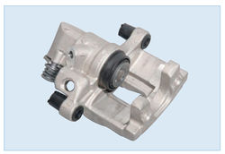
The brake mechanism of the rear wheel is a disc, with a floating caliper, which includes a single-piston slave cylinder. The design of the rear brake cylinder is very complex, because combines a conventional hydraulic cylinder (similar in design to the front brake cylinder) and a parking brake mechanism.
Parking brake actuator on caliper:
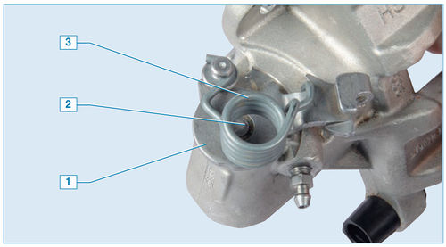
1 - lever;
2 - lever shaft;
3 - returnable spring
The parking brake drive works as follows. The parking brake cable acts on the drive lever and turns it. The spring returns the actuator lever to its original position. The movement of the lever is transmitted to the threaded rod. During lever travel, the lever shaft causes the threaded rod to move out of the cylinder.
Rear brake caliper
Cylinder elements:
1 - threaded rod;
2 - rubber cuff;
3 - threaded bushing;
4 - piston
A bushing is screwed onto the threaded rod, installed in the piston. The threaded bush can be rotated in the piston. Moreover, when the sleeve is pressed against the inner surface of the piston with its conical belt A, turning is very difficult, and if the sleeve moves away from the piston, it turns easily on the thrust bearing. The sleeve in the piston is pressed (through the thrust bearing) by a spring. Thus, as the brake pads wear, the threaded bushing is screwed further from the threaded rod, allowing the piston to exit the cylinder while maintaining a constant parking brake stroke.

Piston elements:
1 - spring;
2 - washer;
3 - thrust bearing;
4 - sleeve cuff;
5 - piston;
A - tapered collar of the bushing

This design of the rear brake cylinder determines the way the piston is recessed into the cylinder when replacing the pads. The piston cannot simply be pushed into the cylinder. Using a lot of force will damage the parts. The piston must be screwed in clockwise and at the same time strongly pressed on it to ensure proper friction along the tapered shoulder and screw the sleeve onto the threaded rod of the parking brake actuator.

Brake pad guide
The shoe guide is attached to the trailing arm of the rear suspension.

Rear brake pads:
1 - inner block;
2 - external block
The inner pads of the rear brake mechanisms are spring-loaded to eliminate vibrations during the operation of the mechanism.

The rear brake disc, unlike the front brake disc, is non-ventilated.

Parking brake lever:
1 - front parking brake cable;
2 - an adjusting nut;
3 - parking brake lever;
4 - parking brake indicator switch
The parking brake lever, fixed between the front seats on the floor tunnel, is connected to two cables through a cable and an equalizer. The rear cable ends are connected to the parking brake actuator levers attached to the rear brake calipers. The parking brake is adjusted by turning the adjusting nut located on the tip of the front cable.
Most vehicles are equipped with anti-lock braking systems (ABS).

ABS unit:
1 - control unit;
2 - hole for connecting the tube of the master brake cylinder;
3 - hole for connecting the brake tube of the left front wheel;
4 - hole for connecting the brake tube of the right front wheel;
5 - hole for connecting the tube of the brake mechanism of the left rear wheel;
6 - pump;
7 - hole for connecting the tube of the brake mechanism of the right rear wheel;
8 - hydraulic block
Brake fluid from the brake master cylinder enters the ABS unit, and from there to the brakes of all wheels.
The ABS unit, mounted in the engine compartment on the left side member, near the bulkhead, consists of a hydraulic unit, a modulator, a pump and a control unit. ABS operates in response to the signals from the wheel speed sensors. The sensors are inductive.

The location of the wheel speed sensor on the steering knuckle
The front wheel speed sensor is installed in the steering knuckle hole and secured with a screw. The sensor drive disk is pressed onto the outer CV joint housing.

Rear wheel speed sensor:
1 - rear wheel hub;
2 - sensor;
3 - sensor fastening screw
The rear wheel speed sensor is attached to the rear wheel hub. If the rear wheel speed sensor fails, the sensor must be replaced.
When the vehicle is braking, the ABS control unit detects the beginning of wheel blocking and opens the corresponding modulator solenoid valve to release the pressure of the working fluid in the channel. The valve opens and closes several times a second, so you can make sure that the ABS is working by a slight tremor of the brake pedal at the time of braking.
ABS has a built-in brake force distribution (EBD) system, which acts as a pressure regulator in the hydraulic drive of the rear wheels brakes. If the rear wheels begin to block when the vehicle is braking, the intake valves of the rear wheel brakes in the modulator switch to the constant pressure maintenance mode, preventing a further increase in pressure in the working cylinders of the rear brakes.
In the event of a malfunction in the ABS, the braking system remains operational, but the wheels may lock. In this case, the corresponding fault code is written into the memory of the control unit, which is read using special equipment at the service center.
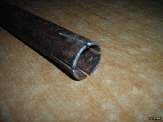
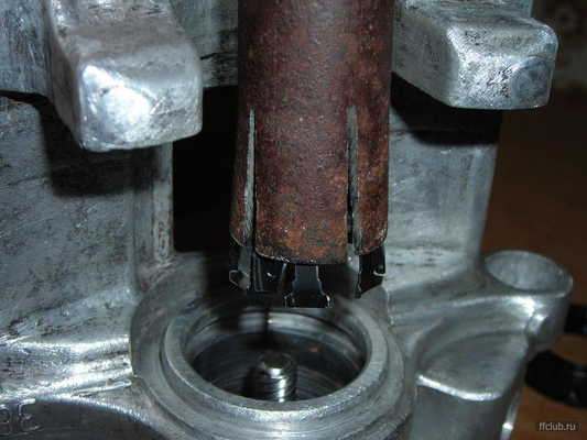

12. Remove the hold-down spring between the caliper and the caliper. You may have to tinker if it sour
This completes the analysis of the caliper.
Here is a photo of the swing arm seat
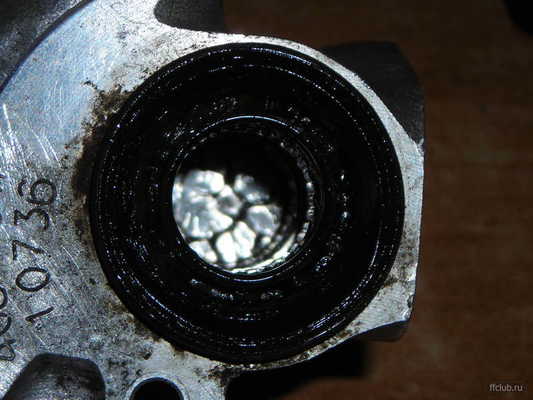
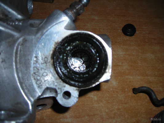

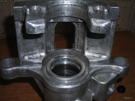
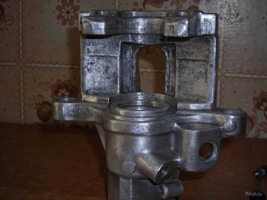

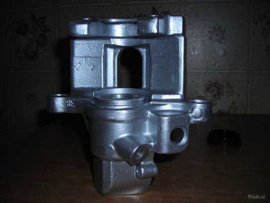
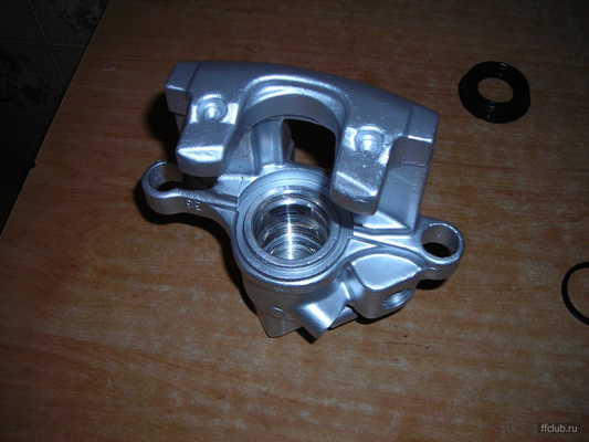

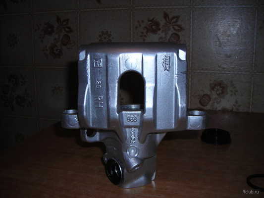

Further assembly in reverse order, applying grease to the required places. Between the flare nut and the piston body, on the piston surface with a thin layer, into the seat of the pivot arm. The boot was washed and smeared with silicone for 3 days. After being wiped off the outside.
—
Well, everyone here is so smart, I just met with a man today and he has a trick of tatal and so on the one hand, the caliper will not put anywhere on the one hand, and the boot is intact
To select an anther, you need to know the diameter of the piston and its maximum stroke. With this information, you can try to pick up a non-original boot in the store.
Or, for example, look here seinsa. es / en / home / home.asp
and for a 2-liter we get a set of kits:
D4365 Repair kit, Caliper | 54 | ATE front caliper repair kit
D4592 Repair kit, Caliper | 57 | ATE front caliper repair kit DIESEL.
D4612 Repair kit, Caliper | 38 | ATE rear caliper repair kit
having fun in Exist we get:
D4365 price 653,49r delivery time 2 days
compound:
Seinsa B7001 Threaded vent plug
Seinsa B6167 Gasket
Seinsa B4381 Bellow
Seinsa B5069 Bellow
Seinsa B5081 Bellow
Well, etc.
You can look for something cheaper.
Due to my own stupidity, I screwed up the rear right caliper. The question arose about replacing it. Prices for new ones, even non-originals, were not at all pleasing.And after a short search on the parsing, a support from a matryoshka with a fomoko stamp was bought for only 1 tr. The external condition was far from presentable. A layer of oxides mixed with dust from the pads, pieces of oxides even under the boot. But the parking brake mechanism worked. And once you bought it, you need to put it in order.
Here is a photo of the insides of the disassembled caliper
1. Clean from dirt, drain the remaining brake fluid
2. Remove the boot by gently prying it with a flat screwdriver around the perimeter. The boot is reinforced with a metal ring.
3. Press out the piston. Can be compressed air or by turning the hand brake lever
4. The piston consists of five parts. Body 2, cone nut 3, bearing 4, washer 5, spring 6. Easily disassembled. It is enough to pick up the edge of the spring and slander it.
5. Remove the O-ring 12
6. Remove the shaped lock washer 7.
7. Remove the spring 8, washer 9, screw 10 and key 11
8. Remove the return spring from the parking brake swing arm
10. Remove the pivot arm stopper.
11. Remove the swing arm
Here is a photo of the swing arm seat
Further assembly in reverse order, applying grease to the required places. Between the flare nut and the piston body, on the piston surface with a thin layer, into the seat of the pivot arm. The boot was washed and smeared with silicone for 3 days. After being wiped off the outside.
Watch an interesting video on this topic
So. A leak was detected from the left rear caliper. Upon detailed examination, it was found that the leak came from under the boot at the entrance of the handbrake lever to this boot. Conclusion - the rear oil seal is leaking. For repairs, a Seinsa D4340 repair kit was purchased (ordered from Exist) - thanks, Lome suggested, but I almost didn't buy a support.
If anyone has a sink - wash it, otherwise everything is in brakes and sand. Next, remove the wheel.
Attention: The photo session began when I removed the caliper. And the shooting process in the photos was actually captured during the installation. Therefore, some bloopers will be traced in the sequence of the described actions and images in the photo. I will pay special attention to this, so as not to mislead.
Attention: The whole process was carried out on a Ford Cougar with a 2.5L Duratec VE engine. But in reality it is the same as if I did it on the Mondeo II.
1. To remove the caliper, it is enough to unscrew just one bolt. You do not need to pull out the hairpin. Remove the cap
To unscrew the bolt, I used an asterisk with an index of 50. I’ll say right away that a day before the start of the whole operation, I sprayed WD-40 into the bolt, into the brake bleed fitting and into the brake hose. Well, just in case. The bolt unscrewed, of course, easily.
2. Remove the parking brake cable
Blooper number 1: there is no bracket in the photo that returns the parking brake lever. I forgot to put it on during assembly. I noticed this already before installing the wheel and put it in place without any problems.
Holding the parking brake lever (you can even move it to the left in this case, it will go easily), use the pliers to disengage the cable retaining ring 1.
Now you need to remove the cable from its attachment point in the caliper. The procedure is not the easiest at first glance. Bracket 2 has three petals, which are unrealistic to bend all at once with a screwdriver, and when released, they return to their place. With the same pliers we grasp the bracket so as to bend two of the three petals, put the cable into the hole, fix it, squeeze the third petal and remove the cable. Next, you need to pass a rubber corrugation through the hole and not damage it. It seemed to me not easy to remove it. I sprayed the corrugation with WD-40 again. If it is stupid to start pulling the cable, then the corrugation gathers in a heap and does not climb. The cable must be stretched by the retaining ring (to the right in this case). Then the corrugation straightens out and passes into the hole quite easily. The cable is removed.
3. Remove the caliper.
We take it to the side and pull it up.
Blooper # 2: Here you can see that the brake hose has already been unscrewed from the caliper. In fact, it is currently still in it.
As I already wrote, it is not necessary to remove the lower hairpin. The caliper is simply grooved onto it.
4. We unscrew the brake hose.
You can't really twist the hose.There you need to make turns 5-6. Therefore, we turn the entire caliper.
Prepare a small wooden wedge in advance. As soon as you unscrew the hose, immediately plug it with a wedge.
Important: in order not to put air into the system, pour the brake into the tank to the eyeballs and close the tank. When the tank is closed, a lot of liquid will not spill out. I got a couple of drops while I put down the caliper and plugged the hose.
For the convenience of work, I washed it with washing powder. Otherwise he was very dirty
Here I already managed to remove the cover from the boot.
5. Remove the bracket:
And remove the boot through the parking brake lever. And now our caliper is ready for repair.
Until now, everything could be done alone, further alone, in my opinion, it is generally unrealistic, especially to collect it in a pile, unless you have a special tool.
7. Remove the ring 1. Next, one person presses on the plate 2, crushing the spring, and the second person pulls out the parking brake lever.
8. We unscrew and take out everything from the caliper.
The culprit was this little oil seal that fits into the groove on the hairpin.
9. Before putting on a new oil seal. We clean the groove from possible rust. We polish as much as we can, this is important.
We put on the oil seal. There is a paint dot on the oil seal. This is done to check if the oil seal is twisted during installation. This is also important. Otherwise it will miss the brake. If there is no mark, then we control it along the seam on the oil seal.
10. Well, since we have dismantled it, then you can change all the other rubber bands - it will not hurt.
We squeeze out the piston and remove the cuff. We'll have to disfigure her, most likely. And then we also remove the inner oil seal (in the photo there is a black ring).
Here is our caliper disassembled. It will not be superfluous to rinse everything again with kerosene and direct the mirror.
11. Install a new internal oil seal. We put the cuff on the piston, insert the piston into the caliper and press the cuff into the caliper.
This must be done carefully. Remember that you have one cuff. The cuff is pressed quite tightly. If you are not sure that you can do this, then it may be better not to do point 10, and therefore point 11.
Important: If the cuff is not changed, then do not use kerosene! He softened her greatly for me. I, too, was not going to change, but I had to after kerosene.
12. Now we collect the back part.
As well as when removing, one person presses on the cup from both sides, for example, with two cylinders (a key for unscrewing the nuts on the wheel, if anyone does not know), and the second inserts a lever and inserts an eccentric into the groove under the lever (the picture shows the groove in the lever under arrow 1). I have not shown the eccentric yet, but it is there (under the lever on the plate), I will show it further.
There is one trick - the threaded pin is not symmetrical at the top. In the upper part, it has a slot, like a screw for a flat screwdriver. Just imagine that this bolt on one side of the slot has a head slightly higher than on the other side. An eccentric is inserted into this slot. Naturally, when you disassemble the support, you don't pay attention to it, but when you assemble it, you scratch your turnips, which side should it be higher, which side should it be lower?
Briefly speaking:
Here, by the way, you can see the eccentric (1) and the upper part of the pin. There is an eccentric between the top of the pin and the lever, which crushes the pin when the handbrake lever is turned.
But here the eccentric is not visible, it is closed by the higher part of the pin (indicated by the arrow) So, the pin is inserted with the lower part towards the shoulder, on which the parking brake cable is attached.
We return to the moment when we crush the bowl with the spring and install the eccentric. We got iterations from the 25th. But when we understood what the trick was, it turned out right away.
- the piston should be almost to the base in the caliper;
- we do everything on a chair. We put two spacers under the caliper (for example, two plywood) so that the piston does not rest on the chair, but is between these spacers;
- one person crushes a plate with two balloons. We do everything on a chair, and not on a table, because then it will turn out, without steaming, to crush a plate with a spring with the weight of the first person;
- the second person first twists the pin with a wide screwdriver until it stops dropping, then crushes it down - and here it becomes clear why two will be placed under the piston - because otherwise you will not crush it, the piston will rest against the chair. After being crushed, without fussing, we put the eccentric (with the thicker side down) and holding it, we start the parking brake lever.
Remember to fit the retaining ring. Blooper # 3: I have it already installed in the pictures.
13. We put on the boot.
14. Install the bracket that returns the parking brake lever. As I already wrote, I forgot to do this and put it on the support already installed in place.
15. We put on the collar. The clamp of the clamp must be in such a place, otherwise the cover will not fit. Well, we put on the lid. We screw in the fitting for bleeding the brakes (if it was unscrewed).
16. It is necessary to align the piston so that it is perpendicular to the wheel axis. There is a protrusion on the brake pad, it must fit into one of the grooves on the piston. The piston turns relatively easily. A screwdriver and a hammer are suitable for this.
This is how it should look like:
17. We install everything in sequence:
- screw the caliper onto the brake hose;
- we put the caliper on the stud and put it in place;
- we fasten the bolt and put a cap on it.
- we pass the parking brake cable into the hole and put the cable ring into the lever.
18. Open the lid of the brake fluid barrel. We release the brake bleed fitting and wait until the cylinder is full - liquid should flow from the fitting (we control the level of the TJ in the barrel). We tighten the fitting. We close the lid of the barrel, after adding the liquid to the maximum.
19. We pump over the brake fluid. It is enough only on this wheel, we monitor the level of TJ.
If, at the time of pumping, the liquid does not leak from anywhere, open a bottle of beer and drink it in one gulp.
Now, like normal engineers, you need to establish the causes of this malfunction. Here's what immediately comes to mind:
1. The rear oil seal was grooved. This can be caused, for example, by sand trapped under the boot. Therefore, the cause may be wear or rupture of the anther. However, upon examining it closely, I did not find any signs of wear.
2. Wear due to age, aging of materials. After all, the car is already 10 years old. Something must break.
Naturally, when you make such a repair, all the time you are under fear that it is about to start flowing again. The oil seal inside its cylinder moves only when the parking brake is tightened and released. Realizing this, you involuntarily pull yourself back when you reach for the handbrake. I began to notice that I was putting on the transmission more and more often. But, probably, this is something from the area of complexes and prejudices. In theory, if everything is done correctly, it will serve as much as a new part.
23.06.2015 2 997

More than a year ago, we talked about how to replace the rear pads with a Ford Focus 1, as well as about replacing the front pads with a Focus 2. The principle is the same, but there are some minor differences.
I will not go into details about why and when it is necessary to change the pads; this is clearly described in the articles above. I propose to go directly to the replacement process.
- Jack;
- Penetrating liquid WD-40;
- A set of keys (Head on: “17-19”, “13”, “15”, etc.);
- Allen key “7”, flat head screwdriver;
- Special "fit" for pressing the brake piston;
- Graphite grease or nigrol, "antiskrip" (if possible);
- New brake pads Focus 2.
1. We put the car on a flat surface, turn on the gear, install chocks or bricks under the front wheels, who is rich in what :-).
2. Next, we rip off the bolts on the wheel, the pads of which are to be replaced.
3. Install the jack and jack the wheel until it comes off the ground.
4. We process the WD-40 connections if necessary and take out the plugs (top and bottom).
5. Take the hexagon at “7” and unscrew the lower and upper guide of the stud.
6. Using a screwdriver, remove the bracket.
7. Now you can remove the brake caliper itself.
eight.We carefully take out the old brake pads, look at the wear, make a decision - to change or leave.
9. To install new brake pads it is necessary to press in (drown) the brake cylinder, this is best done using a special device, on which there are two protrusions that are installed in a sweat on the brake piston. See photo. If there is none on the farm, you will have to twist, you can, for example, try to press it in with your hand or take a bolt, several washers of a suitable diameter and make something similar. The principle is simple - like a corkscrew, you rotate a rod, which rests against one wall, after which the cylinder has no choice but to simply go inside. There are two grooves on the brake piston for the device, we install the device, align the holes and protrusions and twist the piston so that it drowns and allows it to be installed new brake pads for Ford Focus 2.
10. Using a metal brush, we process the shoe seats and put the new brake shoes in place. Draw your attention the fact that the spring block must be installed on the inside of the caliper.
11. Now you can install new pads and put on the brake caliper after cleaning the guides from rust and dirt and lubricating them with graphite grease or in the old fashioned way - with nigrol.
12. Install the guides in place and tighten using the hexagon. Don't forget about the stubs.
13. Install the bracket and handle everything with an “antiskrip”, if any.
14. We hook the wheel and tighten the nuts. After you replace the pads and lower the machine, be sure to retighten the nuts.
Note: Before starting the movement, do not forget to press the brake pedal several times so that the brake cylinder and pads take their places. The first 50-100 km of the brakes you will have "not very", so do not make sudden maneuvers and brake in advance. When the brakes “appear” you will feel it, then you can safely start using it in normal mode.
That's it, now you know how to replace rear brake pads Ford Focus 2.
Thank you for your attention, until we meet again at Ford Master - do-it-yourself Ford car repair. Till!
Good afternoon. Today a Ford Focus 2 came to our car service. He came to us with problems in the operation of the rear brakes. When you press the brake pedal, there is a sound of strong metal-on-metal rubbing. It was decided to remove the wheel and look at the condition of the brake discs and pads. The disc was in good condition, but it was time to change the pads. Therefore, in this article we will show you how to remove and replace the rear brake pads on a Ford Focus 2. It is advisable to perform this procedure every 30-40 thousand kilometers, depending on the driving style.
Vendor code:
Rear disc brake pads - 1 566 096
Tools:
To replace the rear brake pads on a Ford Focus 2, you need a wheel wrench, 7mm sprocket, flat screwdriver
Removing and replacing brake discs on Ford Focus 2:
First of all, we unscrew and remove the rear wheel.
Then remove the spring on the rear caliper.
Then remove the bolt caps on the back of the rear brake caliper.
Next, use a 7mm sprocket wrench to unscrew the upper and lower bolts.
Then it slides the upper part of the brake caliper. We open it.
This is what an open caliper looks like.
We press in the brake cylinder so that new brake pads can be inserted.
After that, insert new Ford Focus 2 brake pads and assemble everything in the reverse order. The whole process of replacing the rear disc brake pads took us about 40 minutes. Before installing the pads, you need to lubricate the guides. Good luck on the road!
If you want to put on more powerful brakes, then replacing the caliper is a must. In this manual, we will show you how to remove and replace the brake caliper on a Ford Focus 2 with your own hands. The process is not complicated and does not require any knowledge of mechanics from you, etc.
You will need: new brake calipers, brake fluid reservoir, 15 "wrench, jack.
We jack the car, remove the wheel and loosen the brake hose.
Unscrew the 2 caliper bolts from the steering knuckle.
We unscrew the brake hose, substitute the empty container and drain the brake fluid. Change and install a new Ford Focus 2 brake caliper and reassemble in the reverse order.
BRAKE Caliper Rear Left FORD FOCUS II Auto Parts ->
Left Rear BRAKE Caliper FORD FOCUS RS MK2 Auto Parts ->
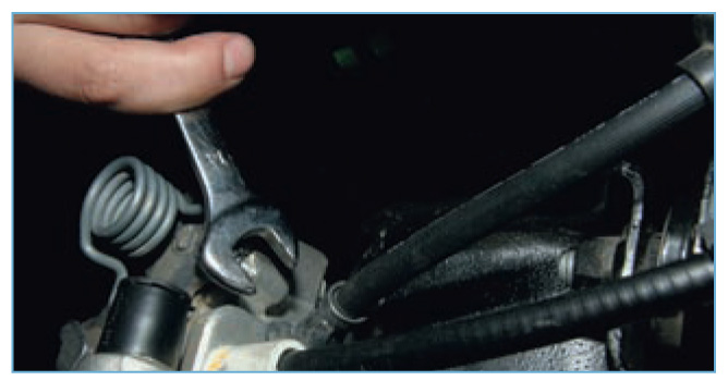
Repair of the rear brake caliper on a Ford Mondeo 2.
File: Repair Ford Focus II-188-6.jpg - Encyclopedia of the magazine "Behind the wheel"
BRAKE Caliper Right Rear FORD FOCUS MK1 Auto Parts ->
File: Repair Ford Focus II-179-3.jpg - Encyclopedia of the magazine "Behind the wheel"
Right rear brake caliper Ford Focus II, Mazda 3, Volvo S40 - Sale of auto parts in Barnaul
Ford Focus 2 Brake system remove replacement repair Ford Focus 2


door sill brake caliper Ford Focus / C-MAX from ASO Auto Parts ->
Rear brake caliper Right for Ford Focus II - 199 rubles. used condition
Rear brake caliper bulkhead on Ford Focus 1
Replacing the caliper Ford Focus 2 2008-2011 with your own hands with photos and videos Avtika.ru
Disc Brake Caliper / - Holder FORD FOCUS Saloon (DFW) 1.4 16V - Allzap
Rear Right support for Ford Focus 3 buy in Sverdlovsk region on Avito - Free ads on the Avito website
Repair Kit, brake caliper ERT 401241
Replacing the caliper Ford Focus 2 2008-2011 with your own hands with photos and videos Avtika.ru
Product search - caliper piston - "AVZ"
Features of the brake system Ford Focus 2 tuning and repair of Ford Focus brakes
SUBSCRIBE TO MY YOUTUBE CHANNEL!
/>
Here you can see my other videos 😉
All my playlists:
/>
* MINI COOPER * Repair and replacement of parts in all models
/>
* FORD * Repair and replacement of parts in all models
/>
* BMW * Repair and replacement of parts in all models
/>
* VOLKSWAGEN * Repair and replacement of parts in all models
/>
* MERCEDES-BENZ * Repair and replacement of parts in all models
/>
* SKODA * Repair and replacement of parts in all models
/>
* VAUXHALL-OPEL Repair and replacement of parts in all models
/>
* AUDI * Repair and replacement of parts in all models
/>
* CHRYSLER * Repair and replacement of parts in all models
Why you can't grease the piston Subscribe to the channel How to make money on your videos AIR affiliate program
| Video (click to play). |
Ford Focus 2 how to eliminate the knock of the rear pads

