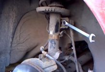
In detail: do-it-yourself repair of the rear beam Lifan Breeze from a real master for the site my.housecope.com.
The Chinese auto industry continually delights us with the release of new car models, which are excellent examples of the best value for money. And one of these cars, which has already gained a high level of popularity in our country, is the Lifan Breez.
The presented car has many interesting technical solutions that retain their maximum simplicity, which is important, especially in terms of the quality level of domestic roads. First of all, this concerns the suspension, which must withstand all the unevenness of the road surface.
The Lifan Breez is equipped with the now classic MacPherson-type front suspension.
It boasts a screw-type spring rod diameter of 12.7 millimeters, as well as an outer diameter of this spring of no more than 145 millimeters. With a free spring height of 45.8 centimeters, we can say that the car is capable of withstanding significant loads. To tighten the spring, you must use a puller that you can make yourself.
The front suspension turns out to be very easy to operate. To dismantle it, you will not need to have specific knowledge.
So, for this you just need to raise the front of the car on a jack, or use a lift, and then unscrew the front wheel. Next, the nuts on the anti-roll bar support are unscrewed, which allows you to get to the support, with its further dismantling. And only after that the three nuts on the ball joint are loosened, by which we provide ourselves with access to the ball joint and the lever assembly. They, of course, also need to be removed.
| Video (click to play). |
Front suspension Lifan Breeze
Removing the front suspension
During reassembly, it is necessary to do all the steps in the opposite order.... Also, it is important to remember about the need to clean all the parts to be installed, replace the installation bolts with new ones, as well as the correct installation of the lever assembly, checking how correctly the silent block is located. The threads of the bolts must be coated with sealant.
The process of checking the technical condition of the suspension is not very difficult, so even novice car enthusiasts can handle it. The first step is to check all parts for deformations and cracks that may occur during operation, especially if significant weight has been applied to the front axle of the car. Next, you need to check that the ball bearing finger moves freely around its axis. The thread must be intact on all turns. If this is not the case, then the defective part must be replaced with a new one.
If you see that you need to replace the lever assembly or the ball joint, then you only need to use new spare parts that have been carefully checked to ensure that the ball hole on the steering knuckle is in good technical condition. If this hole turns out to be larger than necessary, or its shape is not round, then you need to replace the steering knuckle.
The ball pin can be checked for wear without removing it. To do this, you need to raise the car above the ground so that the front wheels do not touch the floor. This will ensure that there will be no significant load on the ball joint pin. Now you need to gently rock the wheel from side to side. In this case, no backlash should be observed. If it is, then this indicates the need to replace the ball joint.
And, of course, it is worth checking the silent block of the lever. If the corresponding hole is enlarged or deformed, it must be replaced.
The suspension of the Lifan Breez car has good properties in terms of resistance to poor road surfaces.
Bottom view of the rear suspension elements
It is made according to the torsion-type scheme. The dimension of the ground clearance without load should be equal to 37.6 centimeters, and with full load - two millimeters more.
The diameter of the torsion bar is 19.3 millimeters. Suspension maintenance requires a standard set of tools as well as a jack or hoist. In the case of a lift, it will be possible to carry out the whole range of diagnostic and repair measures more efficiently.
We raise the car on a lift
In order to remove the rear suspension, you need to raise the car and remove the rear wheels from it. The negative terminal is removed from the battery, and the rear seats, along with the luggage compartment flooring, are completely removed. Also, you will need to dismantle the exhaust pipe and heat shield. The clamp for fastening the "hand" brake, the "spare" and the hook of its bracket, as well as the brake pipes must be disconnected. The jack must be secured against the rear axle connecting pipe in the center section.
Dismantle the rear suspension
Removing the drain spring from the shock absorber
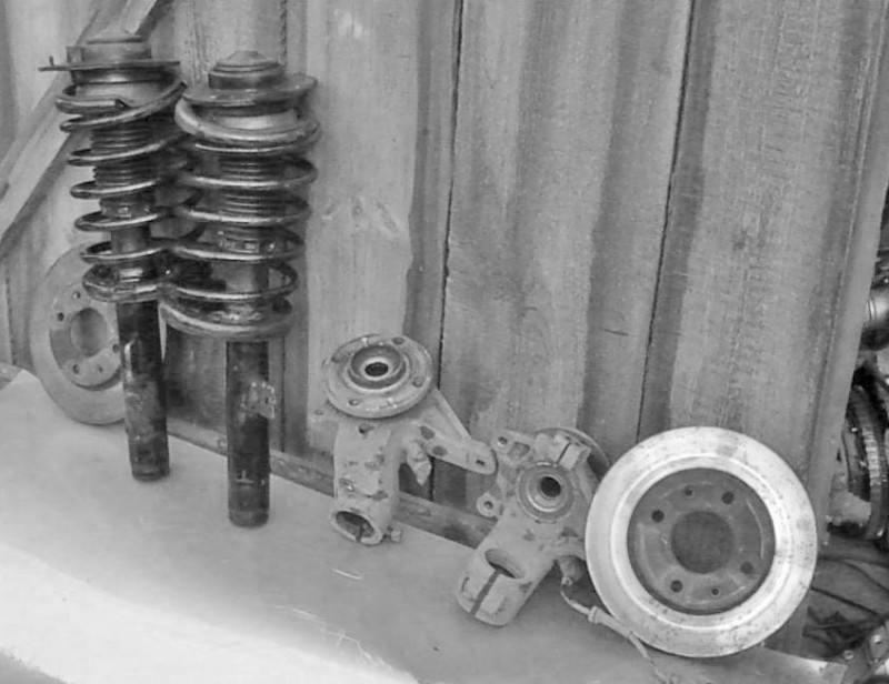
Dismantled elements of the front suspension
Only now can the front and rear support be disconnected, and then carefully lower the jack screw. The car body, after that, is lifted by means of a winch. As a result, we get the ability to dismantle the rear axle assembly with the rear suspension.
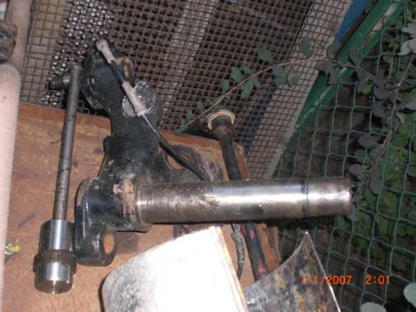
Checking the rear suspension has its own specifics that you need to be aware of. So, in order to make sure that the lower suspension arm is in good condition, you need to do a few things. So, for a start, you need to find a lever, into the hole of which the pipe, axle and axle shaft are pressed. The lever is checked for the possibility of cracks or other defects that have arisen during operation. In case of problems with the axle, you cannot try to straighten it or cook it. It can only be completely replaced. A special press may be required for replacement.
Next, the neck of the axis of the lower arm is checked. It could be physical damage or wear and tear. In case of severe wear, you can try to restore it at a service center, or completely replace it.
Then the surface of the oil seal can be checked. Problems can be wear or shock.
Checking the rear shock absorber for leaks is a good idea. It is difficult to repair, so a complete replacement is recommended. But the bearing can show some problems in operation for various reasons. If we are talking about a lack of lubrication, then it can be topped up. And in all other cases, a complete replacement is required.
Silent blocks, if necessary, must be replaced
In order to purchase parts for your Lifan Breez, you need to know their numbers, by which they can be found in catalogs. For example, for the rear shock absorber, we can talk about the number L2915130, while the front shock absorber should be searched for by the numbers LBA2905110 and LBA2905210 for the left and right, respectively. On sale you can find both original and non-original spare parts. Often, there are no significant differences between them.
We ask all owners of this car to unsubscribe in the comments about the verified parts numbers that you have already installed.
Bought a used car. On an independent diagnosis on the chassis, they said everything is fine, the only thing is to change the bearing at the back. But a week later, there was a terrible creak. I went to my acquaintance, the organ-grinder, who, having examined it, said that one replacement would not be enough. It is necessary to take the complete rear beam assembly. The auto mechanic says that you need to buy not a Chinese one from Lifan, but from a 306 pizho. I don’t know what to do. Advise.
- Messages: 7250
- Location: Rostov-on-Don
- Great wall hover h5 luxe
Do not know. I had a "terrible creak" from behind after the last ford on the pokatushki. Creaked - creaked, but stopped. The reason was a stone between the brake disc and the boot.I fell out myself - I did not have time to get to the highway.
What can “creak terribly” in Lifan, so much so that the beam can be changed? What kind of creak is that? In what modes does it manifest itself? The French have such a sore if they run hard. But there is no creak. There is a knock. And what does Lifan have to do with it? Masters cannot be taken at their word. Because they simply do not exist in their bulk. ... Yes, to the masses. A formless and indefinite mass of uneducated self-taught.
Creaks in almost any mode (I get under way from a place, through the rails, just along a straight line), but not always.
HAPPENS ON THE TRACK when I'm under 100 food .. ONLY THEN AND HAPPENS
SO WHAT DO I GO TO AN OFFICIAL SERVICE?
- Messages: 3236
- BMW X5 4.4
the rear beam is changed if it is bent, and so all the saleant blocks change separately from it, they cost a penny.
Alekzander99, June 13, 2013, 00:04, # 4
the rear beam is changed if it is bent, and so all the saleant blocks change separately from it, they cost a penny.
On our front-wheel drive, it still cracks, then breaks. Maybe it cracked and cracked, and therefore under a replacement?
Garik 2, 13 June 2013, 00:12, # 5
On our front-wheel drive, it still cracks, then breaks. Maybe it cracked and cracked, and therefore under a replacement?
This is the first time I hear it, I don't have it on my dvenashka at all, probably they forgot to put it 🙂
Iugovskikh83, June 12, 2013, 21:25, # 3
Creaks in almost any mode (I get under way from a place, through the rails, just along a straight line), but not always.
HAPPENS ON THE TRACK when I'm under 100 food .. ONLY THEN AND HAPPENS
SO WHAT DO I GO TO AN OFFICIAL SERVICE?
Sell him, 5 years will torture him for a long time.
Russo, 13 June 2013, 01:07, # 6
This is the first time I hear it, I don't have it on my dvenashka at all, probably they forgot to put it 🙂
You haven’t heard a lot about this, but that doesn’t mean that this isn’t happening.
- Posts: 1210
- Location: Siberia.Omsk
- Haima 3
Iugovskikh83, June 12, 2013, 21:25, # 3
Creaks in almost any mode (I get under way from a place, through the rails, just along a straight line), but not always.
HAPPENS ON THE TRACK when I'm under 100 food .. ONLY THEN AND HAPPENS
SO WHAT DO I GO TO AN OFFICIAL SERVICE?
An accurate diagnosis does not interfere. and from him already and dance - "to be or not to be? “. Offs will not bring you to a heart attack.
- Messages: 7250
- Location: Rostov-on-Don
- Great wall hover h5 luxe
Garik 2, 13 June 2013, 07:58, # 8
You haven’t heard a lot about this, but that doesn’t mean that this isn’t happening.
Garik, I listen to authoritative people in this matter 🙂 your previous post smiled.
Russo, 13 June 2013, 10:43, # 11
Garik, I listen to authoritative people in this matter 🙂 your previous post smiled.
Maybe you smile all the time in life, how should I know. And we evacuate front-wheel drive constantly, with a defect in the rear beam in the marked place.
Russo, 13 June 2013, 01:07, # 6
This is the first time I hear it, I don't have it on my dvenashka at all, probably they forgot to put it 🙂
Wait wait. Something I your post did not quite understand. What is not on your dvenashka, rear beams? Burn escho, and go to your authorities, light your pipe and read the primer.
- Messages: 6120
- UAZ Patriot
Lifan breez
Alekzander99, June 13, 2013, 00:04, # 4
the rear beam is changed if it is bent, and so all the saleant blocks change separately from it, they cost a penny.
fuck you please. if you don’t know the system, don’t walk, the suspension in the Peugeot Citroen and Lifan is not dependent and the problem is if you served a big one on time. in a normal scenario, a man with a lifan will only put on 10,000 thousand, with a shitty one for 20,000, and the owners of the French mines for 40 thousand. their parts are many times more expensive
- Messages: 6120
- UAZ Patriot
Lifan breez
about the beam. from Peugeot may not work. at the beginning, order a repair kit for bearings on two sides of the Peugeot 306. on the fingers, if there is a prototype, then they will have to be replaced. fingers separately only on the Internet 1800 finger is worth. do not go to shops because only come with a lever. 5000 thousand rubles each, if not higher. it's hard to disassemble it, to outline the slots on the torsion bars and you also need to get back. the question is, the wheels in your description should stand like a house, when cornering, it seems to steer and the lever does not go up to the lifts. you won't be able to push it like that, but there is a backlash between the beam and the lever. write to me, I have already gone through it. I will tell you what to what in details
As it turned out, I wrote a lot in this message. In the end, I was completely wound up - after all, more than 50 posted photos.But for those who will change the rear beam bearings on their own - do not be alarmed by the volume of what has been written - there are just a lot of pictures and tried to describe in detail the entire replacement process, but in general everything is quite simple ...
So, the first thing - to pull out the torsion bars and the stabilizer, unpress / press in bearings and cuffs, as well as replace the lever fingers (if necessary), the following devices must be made:
Here: with an asterisk - dimensions for reference; rods with an outer diameter of 14 can not be processed, the main thing is that parts (in which holes are 14.2) can freely move along them.
Well, you will also need an M8 nut for the accessories.
2 pieces are made in case one becomes unusable. Or, in the case of barbells - if you have to push one another - to get more swing on impact.
Assembled devices look like this:
a) a device for pulling out the stabilizer
b) a device for pulling out torsion bars
c) devices for pressing out bearings (near and far, respectively) - they differ only in the installed plates
d) devices for pressing the far bearing, the near bearing and the collar, respectively
e) a punch for pressing / pressing the lever fingers
Now that everything is ready, we proceed to the replacement. Of the rare tools, we need a head for 32 (for unscrewing the hub nut). You also need to have a set of good hexagons. I don't remember exactly about the rest of the keys - it seems like nothing special is needed - ordinary running keys / heads.
When I assembled the car, I covered all the bolts and joints with automobile plasticine and grease.
Replacement part numbers:
Rear beam repair kit - SNR KS559.00 (s.)
Includes two bearings (one large - outer, one small - inner) and a cuff with two metal rings under it.
This is all that is needed on one side of the beam (respectively, you need to buy two repair kits).
If you need to replace the lever finger, then its number is Podramnik P-1203 (p.)
If it is necessary to replace the rear beam pipe, then its number is Lifan L2916110 (about 5000 r.)
1. Disassembly and replacement
We will disassemble by hanging the back of the car. We will not disconnect the brake pipes (so as not to engage in pumping the brakes later). I did all the work alone.
1.1. We hang the car (I hung it on stumps) and remove the wheels
This is what the rear suspension looks like from below:
1.2. We take out the hub nut plug from the brake drums
1.3. And we unscrew the hub nuts themselves (with a 32 head)
1.4. Remove the cover (or whatever it is called) of the brake drum
1.5. Next, we remove the brake pads, we tie the brake cylinders with a rope (so that the rods do not jump out of them, and air does not get into the brake system, as a result of which it will be necessary to pump it). Then we unscrew the brake drums from the levers with a hexagon (be careful not to rip off the hexagon in the bolts).
1.6. We unscrew the bolts securing the arm caps on both sides, as well as the plastic bolts (with a hole for an asterisk). We are not trying to remove the plugs themselves. If the plastic bolt breaks off, instead of it you can put a cover for the mirror lining from the gazelle (I changed on both sides for these plugs)
A cover for a mirror facing from a gazelle (if you need to replace your relatives)
1.7. Then, from both sides under the rear beam, we pull out the mounting bracket, and then the brake pipes themselves from the grooves (in order to be able to lower the brake drums). If you break the bracket, then instead of it, like a native, the bracket for the VAZ, GAZ brake hose is suitable.
Brackets for fastening the brake hose VAZ, GAZ (if it is necessary to replace relatives)
1.8. Then, behind the beam, in two places, we disconnect the connectors of the ABS sensors and pull out the part of the wire that goes to the brake discs. At the same time, we remember how they went
1.9. Next, we disconnect the brake cables, ABS sensor wires, brake pipes from all kinds of mounts and lower the brake discs down (onto the stands) so that they do not interfere. But the brake pipes should also hang freely - not taut.
1.10.Now we proceed to the next stage - we take out the stabilizer from the beam. It will come out along with one of the lever plugs. And the second plug will be pulled out separately. For this, our device will come in handy. We screw it into the plug with M12 threads and work like a reverse hammer. We also take out the rubber gaskets and seals on both sides.
1.11. Then we unscrew the bolts (head 21) that attach the shock absorbers to the levers. And disconnect the shock absorbers.
1.12. Now we do what will be useful to us during assembly - we measure the distance from the hub axis to the wing of the car (with an accuracy of no more than a centimeter) on both sides of the car. We will need this when we are going to install the torsion bars back. The minimum error in setting the torsion bar (turning in one tooth) gives a change in this size by about 3-5 centimeters.
1.13. We proceed to pulling out the torsion bars. To do this, unscrew the nut securing the back side of the torsion bar (to the beam) on the left side of the car
1.14. We unscrew the screw and take out the eccentric washer that secures this torsion bar to the right lever
1.15. With the help of the device we knock out this torsion. And we take out this right lever.
Here it is better to act like this - we screw the device with the M8 thread into the torsion bar from the side of the lever (front side of the torsion bar) and start knocking out (working like a reverse hammer). The torsion bar will be knocked out together with this lever. When the reverse side of the torsion bar comes out of the beam hole (this is from the side of the other - the left lever), move the torsion bar away from the hole (in the beam) and unscrew the hairpin from the torsion bar.
Then we unscrew the device from the front side of the torsion bar and screw it here in place of the studs (again on the M8 thread). We take it a little to the side and knock out the torsion bar from the back side - thus, the torsion bar will also be knocked out of the lever. When you take out the torsion bar, screw the stud back into it (so as not to confuse it when installing it). Also, do not confuse it with another torsion bar (they look exactly the same, or rather did not compare)
Note to the photo - instead of the M12 nut (pictured), it is better to screw one of the suitable blanks as part of the device.
1.16. And we take out the cuff (while being horrified by its condition)
1.17. In the same way, we take out another torsion bar: we unscrew the nut that secures it to the beam (the reverse side of the torsion bar)
1.18. On the other hand, unscrew the screw and take out the eccentric washer
1.19. Like the previous torsion bar - with the help of the device, we pull out the torsion bar together with the lever (so that the reverse side of the torsion bar comes out of the beam hole)
And, then, we twist the device on the reverse side of the torsion bar in place of the studs and, taking it a little to the side, we gouge it out from this (reverse) side.
1.20. And we also take out the lever and the cuff.
When you take out the torsion bar, screw the stud back into it (so as not to confuse it when installing it). Also, do not confuse it with another torsion bar (they look exactly the same, or rather did not compare)
1.21. In order to subsequently correctly install the far bearing, before pressing out the bearings, measure the distance from the end of the beam to it (to the far bearing). This can be done with any rod (or you can assemble a device with a blank for installing it and mark it right there). I did it with a rod
1.22. Next, we press out the bearings (for the large - near bearing, we assemble with a larger plate from the device, and for the far - small bearing, we assemble the device with a smaller plate in diameter). We put the desired plate on the device, then the washer, then we tighten the nut. We put the end of the device with the plate behind the bearing, straighten the plate (so that it hooks onto the bearing from behind) and gouge out (like a reverse hammer) all the bearings.
1.23. If any bearing has scattered and any of the seats (under the bearings) of the beam is damaged, then the beam tube must be replaced (to remove the beam, you must unscrew two bolts on each side)
1.24.If it is necessary to replace the fingers of the levers, then we knock out the old finger from the lever and hammer in a new one using a punch (from the device)
1.25. Removing the old rings from the beam
1.26. We remove the old rings from the fingers of the levers (if you changed the fingers, then the rings have already been removed) and press in the new ones (from the repair kit that come with the bearings). It is more convenient to press in by putting the ring on the lever pin and driving the pin into the beam tube
1.27. We press new rings onto the beam (also from the repair kit)
1.28. It would be nice to drill a beam and install grease fittings in it now (like in this photo of a new beam)
2. Assembly
We assemble in the reverse order.
The most difficult thing, as it turned out, was the pressing of the cuff into the ring (which is on the beam). To do this, I changed the original version of the blank (from the device) for installing the near bearing, and made ledges on one side of it for pressing in the cuff. I have not tested this option of pressing.
2.8. Well, the rest is simple - we fasten the shock absorbers to the bolts (there are also fastening of the brake hoses), we fasten the brake drums to the levers, we fix the brake pipes under the bottom (which were disconnected in section 1.7), we connect the wires from the ABS sensors to the connectors (which were disconnected in section 1.7). 1.8), install the brake pads, screw on the brake drum cover and put a plug.
_________________
Lifan Breez sedan 1.6L (China 2008 onwards)
Last edited by Kel_Nerk on Sat Sep 24, 2011 6:53 pm, edited 1 time in total.
resources for uploading photos are full, I use this for the forum, it is enough to indicate the source of the jackdaw in the review, leave it as it is, the photo is automatically optimized, as a result, you get several links, copy it as it is and paste it into the text of your message with all the brackets and that's it
and about the greasers, I stuffed it to such an effort that I had the lithol back through the grease gun a bit, so I suppose the bearings were lubricated even more so under such pressure
_________________
bought in 2009 sold in 2015, generally satisfied.
Section 2: Removing, checking and adjusting the rear axle and rear suspension
I. Dismantling of the rear axle and rear suspension
1. Dismantling the rear axle and rear suspension assembly
1) Install the car, remove the rear wheel bolts, but do not remove them.
2) Raise the vehicle so that both rear wheels are suspended.
3) Disconnect the negative terminal from the storage battery.
4) Remove the rear seats, remove the trunk mat.
5) Remove the exhaust pipe and heat shield on the car floor.
6) Remove the parking brake cable clamp and remove the cable.
7) Remove the spare wheel, spare wheel bracket and spare wheel bracket hook.
8) Disconnect the rear brake lines.
9) Install the jackscrew against the center of the rear axle connecting pipe.
10) Disconnect the front 1 and rear supports 2 from the body (Fig. 3-202), and then slowly lower the jack screw. Remove the front and rear supports 3, use a winch to raise the car body and remove the rear axle assembly with the rear suspension.
2. Disassembly of the rear axle and rear suspension assembly
1) Raise the rear axle and remove the rear wheels.
2) Remove the rear wheel hub: first remove the wheel hub cap, then remove the hub end nut 5 (see Fig. 3-202), then remove the wheel hub 4.
3) Remove the bolts securing the brake shield (rear brake mechanism) to the lower arm 10 and remove the rear brake assembly.
4) Remove the anti-roll bar as shown in Fig. 3-202: Unscrew bolt 6 from the lower arm. Using the special tool 9501-TH 1, screw the screw into the hole of the anti-roll bar to unscrew the plug, remove the anti-roll bar 9 from the other end, pre-apply alignment marks on the lower arm and stabilizer for subsequent assembly.
5) Remove the torsion bar and lower arm.Unscrew the left / right torsion end bolts after making alignment marks (if not present) on the torsion bar and lower arm end face. Remove the lower arm 10 and torsion bar 11 as shown in Fig. 3-202. If it is necessary to remove only the torsion bar from the car, when it is not necessary to remove the lower arm, screw the threaded part of the special inertial puller 1671T into the threaded hole located at the end of the torsion bar, and then remove the torsion bar using an inertial puller.
6) Using the special tool, remove the lower arm needle bearing.
7) Unscrew the upper and lower shock absorber connecting bolts, remove the rear shock absorber as shown in Fig. 3-204. Disassemble the parts as shown in Fig. 3-204, 3-205 and 3-206.
Fig 3-203 Rear axle (suspension) device
1-connecting pipe assembly, 2-upper arm, 3-stabilizer, 4-Front support, 5-rear support, 6-O-ring, 7, 8-Needle bearing, 9-Bolts, 10-Flat washer 11, 12- Left / right torsion bar, 13-arm plug, 14, 15-O-ring, 16-Threaded plug, 17, 30, 31, 32-Washers 18-Threaded plug 19-Stud 20, 21-Bolts 35-36-Bolts
Rice. 3-206 Rear pivot assembly
1-Rear slewing mechanism 2-Axle 3-Axle tube
Rice. 3-207 Checking the journal of the axle of the lower arm and the seat of the oil seal 1-Seat of the oil seal
Figure 3-204 Removing the rear shock absorber 1-Rear shock absorber, 3, 6-Shock absorber mounting bolts 4, 5-nuts, 7-Flat washers
Rice. 3-205 Installing the Shock Absorber Positioning Tool
II. Checking the rear axle and rear suspension
1. Checking the lower arm
The lower arm assembly consists of the arm 1 itself, the axle of the wheel 2 and the axle shaft 3 (see Fig. 3-206). The main component is a lever, into the holes of which the axle tube and the axle shaft are pressed, respectively.
Check lever 1 for cracks or damage, replace if necessary. If the axle tube on the arm is damaged or deformed, do not weld or straighten it, but replace it with a new one. When replacing, use a special tool and a press to press out the axle and install a new one.
Check the lower arm axle journal for wear or damage as shown in Fig. 3-207. If it is severely worn, take it to a qualified repair shop to repair it or replace it with a new one. Replacement must be carried out using a special tool and press. Check the seating surface of the oil seal (see Fig. 3-207) for wear and impact marks.
2. Installing the lower arm
1) Wipe both sides of the oil seal seat clean, apply grease to the leading edge of the new oil seal, and install it in the seat on the lever (see Figure 3-208).
2) With the special tool 9501-T.C. 4 and 9501-T. G 2 install the locking ring in the rear axle and refit them as shown in Fig. 3-209.
3) Apply grease to the lower arm shaft and needle bearing spacer ring. Install the lower arm into the rear axle tube so that the oil seal contacts the circlip as shown in Fig. 3-210.
4) Install the special tool 9501-TG 3 (Shock locating unit) and calibrate the 9501-T positioning tool as shown in Fig. 3-211, then tighten the nuts.
5) According to Fig. 3-212 insert a 0.05 mm gauge between the 9501-T.G3 and the rear axle connecting tube and hitting the lower arm with a mallet, install the arm shaft into the axle tube. If the clearance from point b is 0.05 mm, the installation is correct.
6) Install the torsion bar and its installation bolts according to the alignment marks.
7) Install the rear brake and tighten the bolts to 37 Nm, and then install the brake drum.
8) Remove the 9501-T.G3 and 9501-T Positioning Tool. F1, install the shock absorber, do not fully tighten the bolts.
9) According to Fig. 3-213, install the bolts (M8x1.25) into the anti-roll bar on the left side to fix it for further installation of the right rocker arm.
Figure 3-208 Removing the rear shock absorber
1-Tasks shock absorber 2, 3-Shock absorber mounting bolts 4, 5-Locknuts 6, 7-Flat washers
Rice. 3-209 Fitting the snap ring 1-Snap ring
Rice. 3-213 Left Side Bolt Installation 1-Bolts
Rice. 3-215 Setting the rocker arm
10) Install the rocker arm on the right side in the order shown below: first, thoroughly clean the rocker arm and the inside of the oil seal. Apply MOBILE-MPG 6 grease to the outside of the oil seal and install as shown in
Rice. 3-210 Installation of the lower arm of the rear axle
Rice. 3-211 Setting the Positioning Tool
Rice. 3-212 Setting the Positioning Tool
Rice. 3-214 Installing the oil seal
Rice. 3-210, then use the special tool 9501-T.H2 to install the rocker arm. Install a 1mm plug gauge between the rocker arm and the swivel and tighten the nuts (see Figure 3-215). After the clearance between the rocker arm and the swing mechanism is 1mm, the installation is complete. Then remove tool 9501-I-t2 and tighten the set bolts (see Figure 3-216) to 35 Nm.
11) Apply sealant to the left and right threaded plugs and install them on the left and right side of the rocker arm as shown in Fig. 3-216.
12) Install the wheels and lower the machine.
13) Tighten the wheel bolts and shock absorber mounting bolts.
3. Front self-deflecting elastic base
III. Checking and repairing the torsion spring
If the torsion spring is significantly worn out or the spline connection is incorrectly assembled, the driving comfort and the smooth running of the vehicle will deteriorate. Moreover, when the car is moving on an uneven road, extraneous noise will appear in the suspension. Weakening of the elasticity of the torsion spring, deformation of the spring or abrasion of the mounting end lead to a decrease in the height of the car body, a partial change in the parameters of the position of the front wheels, which negatively affects the stability of the car and causes excessive tire wear. To avoid this, timely replace the faulty torsion spring.
1. Basic notes regarding disassembly and assembly of the torsion spring
1) Before disassembling the torsion spring, note for yourself the relative position of the torsion spring and the shock absorber. When disassembling the shock, install the 9501-T Positioning Tool on the shock and adjust the length.
Rice. 3-216 Tightening the rocker arm set bolts
1- Threaded plug 2-Rocker arm set bolts 3-Threaded plug
Lifan Car Owners and Lovers Club
#1 Prizrak_05 »18 Aug 2013, 13:59
#2 KOSHAN64 »18 Aug 2013, 20:13
#3 breezoman »10 May 2014, 18:26
Prizrak_05
Solution: . nippel.php
Drill, pour nigrol or lithol-24
But this should have been done in the beginning, now you need to repair the beam, for example, rem. SNR rear beam kit KS55900
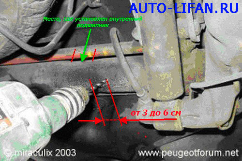
P.S. All suspension parts fit from Peugeot 306
P.S.2. Photo where to drill later:
This publication is the first and so far the only manual in Russian dedicated to the repair and maintenance of the Lifan Breez car with 1.3, 1.6 liter engines. The manual contains detailed technical information, device, wiring diagrams, methods of troubleshooting Lifan Breez / 520 / 520i since 2005 and other models released after 2008
Format: PDF
Size: 152.21 Mb
[url] http://dfiles.eu/files/t8e1a1z85 [/ url]
[B] How to bleed the brake system for Lifan Breeze [/ B]
1) Start pumping the system from the far wheel from the hydraulic modulator.
2) Everything is as usual - remove the rubber cap from the valve, connect a transparent hose to it, lower it into a container with hydraulic fluid and unscrew the valve (key 10).
3) After that:
- Turn on the ignition;
- Press the brake pedal all the way (second person);
- We look at the end of the hose - air bubbles come from there;
- Turn off the ignition.
[B] [U] How to change the cabin filter by re-gluing the filter cloth on lifan 520 breez [/ U] [/ B]
Here is a complete procedure, with explanations in the photo.
1)
2)
3)
4)
5)
6)
7)
Rear beam Lifan Breez 520 L2916103 L2916120 L2916109 L2916125 L2916111 L2916112 L2916104 L2916101 L2916153 L2916151 L2916108 Q151B14115TF3 L2920101 L2920102 L291610716305115 L2920102 L291610716305115 L2940
1. Torsion bar of the rear suspension front Lifan Breez L2916103
2. Rear beam torsion bar D = 18mm Lifan Breez L2916120
3. Rolling bearing of the rear beam Lifan Breez L2916109
4. Lifan Breez L2916125
5. Oil seal rear beam Lifan Breez L2916111
6. Rolling bearing of the rear beam Lifan Breez L2916112
7. Rear suspension torsion bar rear Lifan Breez L2916104
8. Lever tensioning torsion right Lifan Breez L2916101
9. Boot of the lever of the rear beam Lifan Breez L2916153
10.Cap of the lever of the rear beam Lifan Breez L2916151
11. Bearing, rear outer beam Lifan Breez L2916108
12. Bolt Lifan Breez Q151B14115TF3
13. Bump stop lever rear beam Lifan Breez L2920101
14. Cup of a bump stop of the rear shock absorber Lifan Breez L2920102
15. Bearing, rear inner beam Lifan Breez L2916107
16. Bolt Lifan Breez L2916115
17. Lever tensioning torsion bar left Lifan Breez L2916105
18. Suspension arm, rear left Lifan Breez L2916130
19. Rear beam Lifan Breez L2916110
20. Suspension arm rear right Lifan Breez L2916140
| Video (click to play). |
ATTENTION.
new address in Kazan
Uprising 20
tel 8(843)239-20-13
8(937)614-95-66

