In detail: do-it-yourself repair of the rear suspension Passat B5 from a real master for the site my.housecope.com.
The work procedure is applicable for cars:
Volkswagen Passat B5 / Volkswagen Passat B5 (3B2) 1997 - 2001
Volkswagen Passat Variant B5 / Volkswagen Passat Variant B5 (3B5) 1997 - 2001
Volkswagen Passat B5.5 / Volkswagen Passat B5.5 (3B3) 2001 - 2005
Volkswagen Passat Variant B5.5 / Volkswagen Passat Variant B5.5 (3B6) 2001 - 2005
Audi A6 C5 / Audi A6 (4B2) 1997 - 2005
Audi A6 Avant / Audi A6 Avant (4B5) 1998 - 2005
Audi A6 V8 Avant / Audi A6 V8 Avant (4B6) 1999 - 2005
Skoda Superb / Skoda Superb (3U4) 2002 - 2008
I represent my next renovation. About four years ago, I carried out exactly the same operation with the Passat B3, the design of the silent blocks (SB) of the rear beam has changed for the better, simplifying the replacement, but increasing the cost of parts. You will need balloon wrenches, torque wrenches, heads 10, 18, 21 and open-end for 21, a hammer, tape measure and a jack. Here are the silent blocks themselves, I bought BOGE silent blocks, the left and right are different.
First of all, while the car is on wheels, it is necessary to take measurements from the beam in the area of the silent block and to any point on the body, so as not to get on the adjustment of the rear beam at the toe-out stand. Place struts under the front wheel.
Lift one side, remove the wheel and lower the body onto the support (the jack is still needed). For a car with a package for bad roads, remove the protective cover from the silent block by unscrewing the bolt with a 10 key.
Now you need to press the beam up with a jack and you can unscrew the three bolts of the silent block to the body (18mm key) and the SB beam fastening bolt (21mm keys)
| Video (click to play). |
The removed left silent block caused pity. On the right, things were much better.
Now you can install a new silent block. Screw the silent block to the beam but do not tighten, fasten to the body, tighten but do not tighten.
You can put the wheel on and proceed to the second side. When the car is on its wheels, check the dimensions taken before disassembling, if you need to knock the silent block with a hammer to the desired size (the ellipse allows you to adjust about 10 mm), tighten the silent block to the body 110 Nm and turn it 90 °. Set the suspension down by acting on the rear of the machine and tighten to 120 Nm and turn it 90 °. It was not possible to install the cover on the silent block, the design does not allow and the functionality is in doubt.
Then we wash our hands, drink beer and watch football.
If you didn’t find information on your car, look at the cars built on the platform of your car.
With a high degree of probability, the information on repair and maintenance will be suitable for your car as well.
All documentation in English is marked (eng.), In German - (ger.)
For everyone who has a Volkswagen, hands and the desire to do something with them.
For all who has Volkswagen, hands and desire to do something by them.
The work procedure is applicable for cars:
Volkswagen Passat B5 / Volkswagen Passat B5 (3B2) 1997 - 2001
Volkswagen Passat Variant B5 / Volkswagen Passat Variant B5 (3B5) 1997 - 2001
Volkswagen Passat B5.5 / Volkswagen Passat B5.5 (3B3) 2001 - 2005
Volkswagen Passat Variant B5.5 / Volkswagen Passat Variant B5.5 (3B6) 2001 - 2005
Sooner or later, any unit requires either repair or replacement.
In this case, the silent blocks of the rear beam VW Passat b5.
I think that you shouldn't write how to jack up the car and remove the wheel and make the process safe .. or if you don’t know it it’s better not to go in there!
1) The beam is attached to two brackets. The bushings are actually located in the brackets.
2) It is better to remove the brackets in turn, so it is easier not to knock down the position of the beam so that later you do not go to the camber
You will need two 21mm keys (or 21mm heads if you can get in there)
The bracket is attached to the body with bolts, which are unscrewed by the head by 18mm.
3) now about replacing the silent block itself
You can certainly buy ready-made brackets with silent blocks .. but it's more expensive and not so interesting.
Therefore, silent blocks were purchased separately from the brackets.
we will install them.
4) to remove the old one, you need to make two cuts with a grinder. So that an emphasis appears, or you can squeeze out the silent block only in one direction.
5) Extrude with a press.
The clip must be matched to the outer diameter ..
in my case from the front hub bearing Hyundai Getz
6) we clean the seat.
and press the new silent block with the same clip
Press into the bracket according to the same position as the previous one.
7) install the bracket on the body according to the old marks .. they can be seen on the bolt washers and on the body itself.
and only then we fasten the beam to the bracket!
Finally, I advise you to tighten the bolt after the car is on its wheels.
access is enough .. so silent blocks will live longer!
On the other side, we do the same.
Time spent on both sides 2 hours.
Expenses for two silent blocks 1500 rubles
instead of 5-7 thousand which are assembled with brackets ..
Maybe someone will find my theme useful ..
If you didn’t find information on your car, look at the cars built on the platform of your car.
With a high degree of probability, the information on repair and maintenance will be suitable for your car as well.
All documentation in English is marked (eng.), In German - (ger.)
For everyone who has a Volkswagen, hands and the desire to do something with them.
For all who has Volkswagen, hands and desire to do something by them.
Rear suspension for front wheel drive vehicles
Rear suspension elements for front-wheel drive vehicles
9 - bolt М12х1.5х60, 110 Nm + turn 90 °,
10 - rear beam,
11 - bolt М14х1.5х190, 120 Nm + turn 90 °,
12 - stabilizer lock,
13 - threaded hole,
A - the direction of movement of the car,
B - the right side of the car


Shock absorber for front wheel drive vehicles
1 - gas-filled shock absorber,
2 - nut,
3 - bolt М10х90, 50 Nm + turn 90 °,
4 - protective casing,
5 - protective cover,
4 - protective casing,


The base of the rear suspension is a beam with levers welded to it. A stabilizer is installed in front of the rear beam, which reduces the car's roll when cornering. The rear beam is attached to the body through rubber-metal bushings. Separate springs and shock absorbers are used to cushion the rear beam. As a result of the separate arrangement of the rear suspension springs, the volume of the luggage compartment has increased.
Rear suspension beam for all-wheel drive vehicles
the multi-link suspension has a big advantage over the beam used on previous generations of VW. It improves handling, stability and comfort. But due to the sheer amount of detail, it can also be a weak point. Natural wear and tear of any (of the many) silent blocks turns the "assembled" machine into a roll barge that responds to the rut and road profile.
The weak points in the rear suspension include the front wishbones.
They have the smallest silent blocks with long suspension travel.
The most annoying thing is that it is not very easy to calculate their wear if you do not know how to check, where to look and what needs to be seen there. To begin with, the wear of the silent blocks in these levers gives the wheel some freedom of movement relative to the body.
only if you use two stops at once, you can unload these levers, and feel the bumpiness with your hands.
But there is another way to recognize a malfunction: hang the car and pull back the levers with a bar. Then you can see the peeling of the rubber
So, the verdict has been delivered. You can completely replace these levers on your own.
now in color pictures, and with slight simplifications. For example, it is not necessary to remove the springs at all.
-Before starting dismantling, it is necessary to clean and fill with a "liquid wrench" all the bolts
- the need to unscrew the stabilizer is due to the fact that the inner bolt abuts against it
but in fact, it is not necessary to unscrew the struts from the lever, the internal bushings are enough - from the body
by unscrewing the brackets, the stabilizer can be lowered, and it no longer interferes with removing the bolts
-Now you can unscrew the bolts of the levers
-take out the old levers, take out the new ones from the packaging. According to ELSA, they are symmetrical and non-symmetrical, i.e. left and right
before building, read ELSA again:
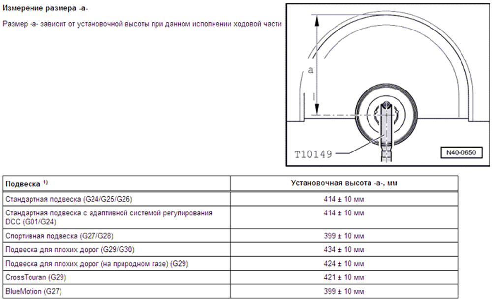

and again we pass from theory to practice:
-Selecting the correct lever, insert it into the frame
-If a new, but not the original, lever is installed, you can simplify the next replacement (which, of course, will soon be required) by inserting the internal bolts from the other side
-However, you first need to either shorten the bolt by 5 mm, or put another washer, otherwise the tip of the bolt will rest against the stabilizer
-insert the outer bolt. When the wheels are hanging, there is a divergence of the planes, so the bolt must be pulled down a little and at the same time push
- we press on several turns of the nut, but before tightening, you need to give the lever a position similar to the one loaded by the weight of the car
-that now you can tighten both bolts of the lever
-when both levers are hung out again, bait and tighten the stabilizer bolts
-Now you can tighten the wheels, lower the car and go straight to the camber / convergence stand. And rejoice that the car is going straight again, like a tram on the rails.
Various types of suspensions are available for the vehicle as additional equipment. The suspension type is indicated by a PR number. The PR number of the suspension can be found on the vehicle data plate located in the luggage compartment to the left of the spare wheel. Also, the PR number is given in the car's service book.
The information is intended for models 2000, 2001, 2002, 2003, 2004, 2005 model year.
Pressing the upper arms out of the stub axle, see here
Removal and installation of the front lower arm see here
Replacing the front lower arm bushings, see here
Removal and installation of the rear lower arm see here
Replacement of the rear lower arm bushing and anti-roll bar bushings, see here
Removal and installation of the upper suspension arms and replacement of the bushings of the upper arm supports, see here
Removal and installation of the stretcher see here
Replacement of the subframe support, see here
Removal and installation of the shock absorber, see here
Disassembly and assembly of the shock absorber, see here
Removal and installation of the pivot pin see here
Disassembly of the stub axle see here
Removal and installation of a semi-axle with hinges of constant angular velocities, see here
Semiaxis repair see here
Removal and installation of the rear axle beam and shock absorber spring, see here
Removal and installation of the hub unit see here
Anyone who can withstand the reading of my renovation, and find inaccuracies in the names, let them forgive me.
I'm not an auto locksmith, this is not mine.
But I love my car and everything is made for it.
I'm not a magician, I'm just learning.
Assembled in reverse order or as it turns out.
Recommendation: before connecting the shock absorber strut assembly (assembled), it is necessary to connect No. 16 - shock absorber strut and No. 23 - M12x1.5x85 bolt.
Then it will be easier to make the connection of the rack to the body, and to carry out item # 8.
All bolts, nuts and parts were unscrewed without problems. With a great desire, you can use VD-40 or substitutes.
Run across Moscow and Obl. over 21,000 km.
Repair tools:

Taking this opportunity I express my deep gratitude and wish you prosperity in business:
AXL for timely advice and clarification on leverage and of course for bringing us all together.
ANDREW for a good discount on a set of levers and every little thing.
ARA for help in changing the tariff plan and connecting to the Internet.
Do not be afraid to make repairs, it is not as scary as I described.
I wish YOU success in the repair and the car will say THANKS to YOU.
REMOVAL AND INSTALLATION OF THE LONGITUDINAL ARM WITH SUPPORT BRACKET
- Withdrawal
- Remove the wheel.
- Remove the coil spring.
Remove fastener 1 by pressing out the inner rivet shafts (fig. 1).
Unscrew the connecting rod 2 from the trailing arm.
Unclip the electrical cable from the clip on the support bracket.
Mark the mounting position of the support bracket on the body.
Remove the trailing arm 1 with a support bracket (fig. 2).
If necessary, replace the trailing arm by removing the support bracket from the arm.
Clamp the trailing arm in a vise so that the support bracket 1 touches the vise (Fig. 3).
Unscrew bolt 2. In this case, it is necessary to adjust the mounting position of the support bracket relative to the trailing arm.
Determining the mounting position of the support bracket relative to the trailing arm
Measure the size "a»From the center of the bolt to the outer edge of the support bracket. Dimension a is 57.5 ± 1 mm.
After setting dimension a, tighten the bolt.
The threaded connection of the trailing arm to the wheel bearing housing can only be tightened if the remaining parts (spring and shock absorber are required) of the corresponding wheel suspension are already installed. When tightening, the wheel suspension must be unsprung. Only now the trailing arm and wheel bearing housing move to the desired position (fig. 5)
When performing the following operations, the sequence of actions must be strictly followed.
Install the trailing arm and support bracket with bolts to the wheel bearing housing without tightening.
Insert the connecting rod 1 into the trailing arm without tightening the nut (fig. 6)
Raise the wheel suspension using the engine / gearbox strut and support until the support bracket contacts the body. Tighten the bolts to the old mark.
Lower the wheel suspension on the strut again and remove the support from the hub.
Install the coil spring.
Tighten the trailing arm bolts to the correct torque while making sure the parts are in the correct position.
Tighten the tie rod nut on the wheel bearing housing.
Remove the fastener by pressing out the inner rivet shafts.
Install and screw on the wheel.
Adjust the wheel alignment angles.
LONGITUDINAL ARM REPAIR
Pressing out the rubber-metal sleeve
Clamp the trailing arm in a vise so that the support bracket 1 touches the vise (fig. 7).
Install the tools as shown in Figure 8.
Press out the rubber bushing.
Pressing in the rubber-metal sleeve
Place the trailing arm on a flat surface.
Install the trailing arm on a plane so that the dimension "a" was equal to 113 mm (Fig. 9).
Mark a vertical line on the trailing arm bushing.
Position the rubber-to-metal bush on the trailing arm so that the marked line is between the lugs 1 (fig. 10).
Ensure the correct installation position of the rubber-metal bushing relative to the trailing arm bushing.
Install the tools as shown in the figure (fig. 11).
Press the rubber bushing flush.
Install the support bracket to the trailing arm.
Rice. 5.4.6. ... and remove the pinch bolt from the steering knuckle
Rice. 5.4,v. Disconnect the ball joints from the steering knuckle
Rice. 5.6. Upper arm bracket bolts (indicated by arrows)
1 Chock the rear wheels, jack up the front of the car and
place it on the stands. Remove the corresponding front wheel. After removing the wheel, screw the bolt into the hub to hold the brake disc in place.
2 On cars with lobsters with automatic beam height control, disconnect the vehicle's ground clearance sensor rod from the front lower wishbone (see chapter 12).
3 Disconnect the ABS wheel sensor wire from the mounts.
4 Unscrew the retaining nut and remove the pinch bolt from the top of the steering knuckle. Disconnect the ball joints of the front and rear upper control arms from the steering knuckle, but do not open the ties with a screwdriver or something similar (Fig. 5.4, a - c). Work carefully: do not damage the ball finger covers.
5 Unscrew the nut and remove from the front lower arm the bolt securing the strut from below (see paragraph 4).
6 The mounting bolts of the upper suspension arms can be unscrewed in the engine compartment (fig. 5.6). Remove the 3 bolts and upper control arm bracket, suspension strut and upper control arm assemblies. Perhaps plastic washers will be installed under the bolts: they do not need to be installed during assembly, this is done by the automaker for technological purposes.
Note: Mark the position of the shims under the upper arm bracket bolt heads. When assembling, they need to be installed in the same way. as they were installed prior to removal.
7 Clamp the lower end of the stand in a soft-jaw vise. Unscrew the nuts and remove the bolts securing the upper levers to the bracket (Fig.5.7).
8 Thoroughly remove any dirt, grease or thread glue from the arms and the area around them. Inspect all parts for damage and cracks. Pay particular attention to the arm bushings and ball joints. The ball joint cannot be separated from the lever. If the support or arm is damaged and requires replacement, they must be replaced together.
9 Replacing the inner bushing requires a hydraulic press, so it is best to have this work done by a VW dealer. If you have a press and a corresponding set of spacers, then press out the old bushing and press the new one through the spacer resting only on the outer surface of the bushing. Make sure the bushing is installed properly as shown in fig. 5.9.
10 Attach the arm to the upper arm bracket, insert a new bolt into the bushing and screw on a new nut.
11 Install the lever so that the distance between the front edge of the bracket and the lever is 47 mm (fig. 5.11). While holding the lever in this position, tighten the nut to the first tightening torque and tighten by the second tightening angle. Thanks to this, the rubber bush will not be “kinked” after the vehicle is mounted on the wheels.
12 Install the stand. Brackets, levers. According to the marks you made before removal, install the bracket, its upper bolts and spacers. Tighten the bolts to the specified torque.
13 Insert the bolt securing the lower end of the strut to the wishbone. Screw on a new nut by hand.
14 Insert the upper arm ball joints into the steering knuckle. Insert the tie bolt and screw a new nut onto it.Tighten the nut to the required torque (Fig. 5.14). When tightening the nut, push down on the levers so that the ball joints sit in place properly.
15 Install the ABS sensor wire to the mountings.
16 On vehicles with headlamps with automatic beam height adjustment, connect the vehicle's ground clearance sensor rod to the front lower arm (see chapter 12).
17 Install the wheel, tighten the bolts to the specified torque and lower the car to the ground.
18 With the vehicle on wheels, tighten the nut that secures the lower end of the strut to the arm to the required torque. 19 Check and, if necessary, adjust the front toe-in at a VW dealer workshop or any other suitably equipped station.
Rice. 5.7. Bolts / nuts securing the upper arms to the bracket (shock absorber removed for clarity]
Rice. 5.9. Install the bushing in the lever correctly.
Rice. 5.11. Install the arm so that the distance between the front edge of the bracket and the arm is 47 mm
Rice. 5.14. Tighten the new nut to the correct torque
Lower rear suspension arm Withdrawal
20 Put chocks under the rear wheels, jack up the front of the car and place it on the stands. Remove the corresponding front wheel. After removing the wheel, screw the bolt into the hub to hold the brake disc in place.
21 Unscrew the retaining nut, disconnect the lever from the steering knuckle using a ball pin puller. Do not damage the cover of the ball joint (Fig.5.21 .a, b).
22 Unscrew the nut of the inner (in relation to the vehicle) bolt securing the suspension arm. To remove the bolt, you need to slightly lower the corner of the subframe. To do this, unscrew the 2 bolts of the subframe bracket. Unscrew and remove the front attachment subframe. Note that the bolt is inserted into the inner hole of the subframe.
23 Lower the subframe slightly, remove the bolt and remove the arm from the vehicle.
24 Thoroughly clean the lever and the adjacent surface of any dirt, grease or thread glue. Inspect all parts for damage and cracks. Pay particular attention to the arm bushing and ball joint. Note that the inner sleeve is backed up. If traces of fluid leakage are visible near the bushing, then the bushing needs to be replaced. The ball joint cannot be separated from the lever. If the support or arm is damaged and requires replacement, replace them together.
25 Replacing the inner bushing requires a hydraulic press, so it is best to have this work done by a VW dealer. If you have a press and a corresponding set of spacers, then press out the old bushing and press the new one through the spacer resting only on the outer surface of the bushing. Make sure the bushing is installed properly so that the arrows or groove point towards the ball joint (fig. 5.25).
26 Installation is carried out in the reverse order of removal, but note the following:
a] Install new bolts and nuts securing the subframe and arm.
b] The inner bolt securing the lever must be tightened to the required torque under load, on a car resting on its wheels.
c) Make sure the inner bolt securing the arm is inserted into the inner hole on the subframe.
d) Tighten the threaded connections with the required torques, if the tightening torques for these connections are specified.
Front lower suspension arm
27 Put chocks under the rear wheels, jack up the front of the car and place it on the stands. Remove the corresponding front wheel. After
When removing the wheel, screw the bolt into the hub to hold the brake disc in place.
28 On vehicles with headlights with automatic beam height control, disconnect the vehicle's ground clearance sensor rod from the front lower wishbone (see chapter 12).
29 Unscrew the retaining nut, disconnect the lever from the steering knuckle using a ball pin puller. Do not damage the ball joint cover.
30 Unscrew the nut and remove the bolt securing the lower legs of the rack to the arm.
31 Unscrew the nut and disconnect the anti-roll bar from the arm as described in paragraph 6.
32 Unscrew the nut and remove the inner bolt holding the arm. Remove the lever. Note that the bolt is inserted into the inner hole of the subframe.
33 Thoroughly remove any dirt, grease or thread glue from the arm and the adjacent surface. Inspect all parts for damage and cracks. Pay particular attention to the arm bushing and ball joint. The ball joint cannot be separated from the lever. If the support or arm is damaged and requires replacement, they must be replaced together.
34 Replacing the inner bushing and the bushing to which the lower end of the strut is attached requires a hydraulic press, so it is best to have this work done by a VW dealer. If you have a press and a corresponding set of spacers, then press out the old bushing and press the new one through the spacer resting only on the outer surface of the bushing. Make sure the bushing is installed properly as shown in fig. 5.34.
35 Installation is carried out in the reverse order of removal, but note the following:
a] Install new bolts and nuts securing the arm and arm to the arm.
b] Nut securing the inner end of the growlingha, the nut that secures the lower end of the rack to the arm and the nut of the anti-roll bar must be tightened to the required torque under load, on a car resting on its wheels.
c) Make sure the inner bolt securing the arm is inserted into the inner hole on the subframe.
d] Tighten the threaded connections with the required torques, if the tightening torques for these connections are specified.
Rice. 5.21, a. Ball pin remover ...
Rice. 5.21, b. ... disconnect the lower rear arm from the steering knuckle
Rice. 5.25. Make sure the bushing is installed so that the arrows (1) or groove (2) point towards the ball joint.
Rice. 5.34. The sleeve must be installed so that the dimension 'a' is B '± 3'
Front wheel drive cars
Rear suspension for front wheel drive vehicles
Rear suspension elements for front-wheel drive vehicles
9 - bolt М12х1.5х60, 110 Nm + turn 90 °,
10 - rear beam,
11 - bolt М14х1.5х190, 120 Nm + turn 90 °,
12 - stabilizer lock,
13 - threaded hole,
A - the direction of movement of the car,
B - the right side of the car
Spring 4 must not have damage to the lacquer coating.
Before installation, clean the bearing surfaces of the rubber-to-metal support bracket. 6. After installation, check and, if necessary, adjust the rear wheel track.
When installing nut 7, it is recommended to use a new nut.
When installing bolts 8, 9, 11, it is recommended to use a new bolt.
Clean the support surfaces of the rear beam 10 before installation.
Shock absorber for front wheel drive vehicles
1 - gas-filled shock absorber,
2 - nut,
3 - bolt М10х90, 50 Nm + turn 90 °,
4 - protective casing,
5 - protective cover,
4 - protective casing,
Replacement of shock absorber 1 is made assembled.
When installing nuts 2, 9, it is recommended to use new nuts. When unscrewing nut 9 with a second wrench, keep the shock absorber rod from turning.
When installing bolt 3, it is recommended to use a new bolt.
The base of the rear suspension is a beam with levers welded to it. A stabilizer is installed in front of the rear beam, which reduces the car's roll when cornering. The rear beam is attached to the body through rubber-metal bushings. Separate springs and shock absorbers are used to cushion the rear beam. As a result of the separate arrangement of the rear suspension springs, the volume of the luggage compartment has increased.
4 wheel drive cars
Rear suspension beam for all-wheel drive vehicles
Volkswagen »Volkswagen Passat» Passat B5, »Suspension» Front suspension. Front suspension arm set for Passat B 5 (RUVILLE), analog.
Convergence curve, trade wind b 5, super B, audi, stretcher adjustment.Passatuk last online 8 hours ago. Features of a multi-link suspension. Toe Curve Controls each of the trapezoidal wishbone front wheels on.
Suspension arm Volkswagen Passat B 5. FRONT SUSPENSION LEVER UPPER LEFT REAR Year of issue: 1997 - Original number.
The suspension is installed on the lift at the points marked in the figure - these are bolted connections with which the subframe is attached to the body. To do this, you need to loosen the eight bolts with which it is attached to the body. In the first development of such a suspension model, certain design flaws were identified. But still, there are ways to do without such a device and achieve the necessary indicators of variable convergence. Run across Moscow and Obl.
And what could be more understandable for an auto mechanic than trying it yourself! The cost of this device is about a thousand conventional units, which raises the question of the expediency of its use. The technical task to develop the details of such a suspension was transferred to several large manufacturers of parts for the development of components for mass production. Maintenance kits with original VAG oil On the site> added kits for routine maintenance of the car, with original consumables fil.
Adjustments on a specific example As an example to consider the nuances in working with a four-link aluminum suspension, we will give the parameters for the Skoda Superb. In practice, the opposite often happens - a domestic mechanic, tracing his relationship with the greatest inventor and master Kulibin, undertakes to repair everything. From the inner side of the wing, remove the lock nut and pull the strut assembly down.
The difference in convergence at two points is several minutes, that is, it is a very thin value that is not easy to catch experimentally. Particular attention should be paid to the vehicle year line. They provide the redistribution of driving and braking forces between the wheels, the desired behavior in corners, etc.
If not long ago the multi-link aluminum suspension was the prerogative of expensive cars, today it is increasingly used in small cars.
Replacing the lower arm of the front suspension. Audi A4 / Passat B5

Rear suspension for front wheel drive vehicles
1 - shock absorber, 2 - spring, 3 - beam, 4 - upper spring support, 5 - shock absorber support, 6 - buffer, 7 - brake disc, 8 - bearing, 9 - stabilizer, 10 - handbrake cable, 11 - rubber-metal support
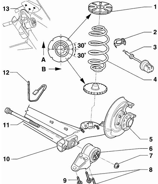
Rear suspension elements for front-wheel drive vehicles
1 - upper spring support, 2 - wheel rotation sensor holder, 3 - wheel rotation sensor, 4 - spring, 5 - hub bearing, 6 - rubber-metal support with bracket, 7 - nut, 8 - M12x1.5x90 bolt, 110 Nm + tighten 90 °, 9 - M12x1.5x60 bolt, 110 Nm + turn 90 °, 10 - rear beam, 11 - M14x1.5x190 bolt, 120 Nm + turn 90 °, 12 - stabilizer lock, 13 - hole threaded, A - direction of movement of the car, B - right side of the car
The prevention The spring 4 must not have damage to the varnish coating.
Before installation, clean the bearing surfaces of the rubber-to-metal support bracket. 6. After installation, check and, if necessary, adjust the rear wheel track.
When installing nut 7, it is recommended to use a new nut.
When installing bolts 8, 9, 11, it is recommended to use a new bolt.
Clean the support surfaces of the rear beam 10 before installation.
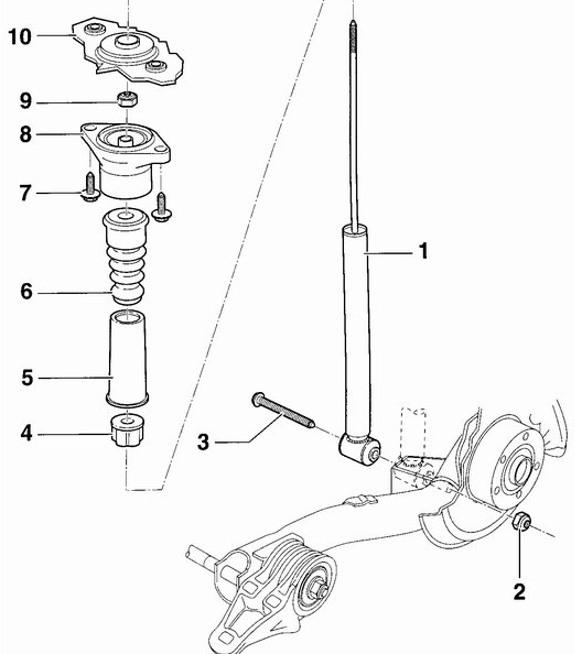
Shock absorber for front wheel drive vehicles
1 - gas-filled shock absorber, 2 - nut, 3 - M10x90 bolt, 50 Nm + turn 90 °, 4 - protective cover, 5 - protective cover, 4 - protective cover, 5 - protective cover, 6 - buffer, 7 - bolt , 45 Nm, 8 - upper shock absorber mounting, 9 - self-locking nut, 25 Nm, 10 - threaded holes in the car body
The prevention Replacement of the shock absorber 1 is made assembled.
When installing nuts 2, 9, it is recommended to use new nuts. When unscrewing nut 9 with a second wrench, keep the shock absorber rod from turning.
When installing bolt 3, it is recommended to use a new bolt. The base of the rear suspension is a beam with levers welded to it. A stabilizer is installed in front of the rear beam, which reduces the car's roll when cornering. The rear beam is attached to the body through rubber-metal bushings. Separate springs and shock absorbers are used to cushion the rear beam. As a result of the separate arrangement of the rear suspension springs, the volume of the luggage compartment has increased.
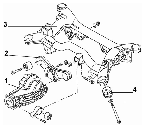
Rear suspension beam for all-wheel drive vehicles
1 - rear final drive, 2 - bracket, 3 - beam, 4 - rubber-metal support
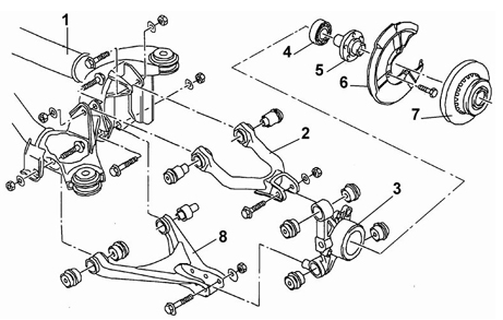
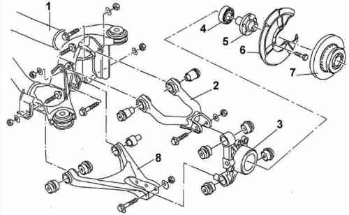
Rear suspension arms for all-wheel drive vehicles
1 - beam, 2 - upper arm, 3 - hub fastener, 4 - bearing, 5 - hub, 6 - shield, 7 - brake disc, 8 - lower arm
The rear suspension consists of a double wishbone beam and shock struts on each side of the vehicle. The beam is attached to the car body with four rubber-metal bearings. The prevention Welding and straightening works are not allowed on the load-bearing elements of the rear suspension. When installing, it is necessary to use new self-locking nuts and replace the bolts that show signs of corrosion.
Unscrewing the upper shock absorber mounting
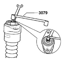
Using a VW-3079 wrench to keep the shock absorber rod from turning when unscrewing the shock absorber upper mounting nut
When unscrewing the nut of the upper mounting of the shock absorber using a VW-3079 wrench, keep the shock absorber rod from turning.
Removal and installation of shock absorber and spring
The information in this subsection applies to front wheel drive vehicles.
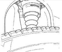
The location of the bolts of the upper mounting of the rear shock absorber
Elements of the lower mounting of the rear shock absorber
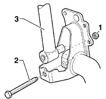
1 - nut, 2 - bolt, 3 - shock absorber
1. On a car standing on wheels from under the car, unscrew the bolts of the upper fastening of the shock absorber to the car body. To improve access to the shock absorber mounting bolts, the vehicle can be raised slightly. 2. To relieve the rear suspension spring, raise the rear of the vehicle until the wheel is 10 cm off the ground. Remove the rear spring from the supports and remove it from under the vehicle. If necessary, the second person should turn the rear suspension beam downward. 3. Unscrew the nut and remove the shock absorber lower mounting bolt. Moving up, remove the lower part of the rear shock absorber from the rear beam, lower the shock absorber and remove it from under the car Installation
1. Install the shock absorber in place, insert the shock absorber mounting bolt and screw the nut onto it without completely tightening it. 2. Install the spring so that the outermost turns of the spring are located on the supports in such a way as shown in fig. Correct positioning of the lower coil of the spring in the spring seat. 3. Screw the upper shock absorber mount to the vehicle body. 4. Lower the vehicle to the ground so that the rear wheels are on the ground, but the bolts of the upper mounting of the rear shock absorber can be accessed. 5. Tighten the rear shock absorber upper mounting bolts to 45 Nm. Tighten the bolt and nut of the lower mounting of the rear shock absorber to 50 Nm and then turn it 90 °.
Removing and installing rear wheel bearings / hubs
Rear Wheel Bearing / Hub Fasteners on Front Wheel Drive Vehicles
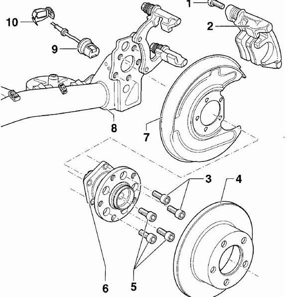
1 - self-locking bolt, 35 Nm, 2 - rear brake caliper, 3 - bolts, 60 Nm, 4 - brake disc, 5 - bolts, 60 Nm, 6 - bearing / rear wheel hub, 7 - tamped casing, 8 - rear beam , 9 - rear wheel rotation sensor, 10 - rear wheel rotation sensor retainer
The prevention At installation of bolt 1 it is necessary to use a new bolt.
The bearing / hub of the rear wheel 6 is a single unit.In this case, adjustment of the rear wheel bearing is not required.
1. Unscrew the two bolts of the brake caliper, while using a thin wrench, keep the guide pin from turning.
2. Remove the brake pads. 3. Remove the brake disc. 4. Through the hole in the hub, unscrew the five bolts securing the bearing / rear wheel hub.
5. Remove the rear wheel bearing / hub. Installation
1. Install the bearing / hub of the rear wheel and screw in with the bolts, tightening them to a torque of 60 Nm. 2. Install the brake disc. 3. Install the brake pads. 4. Install the brake caliper and secure it with new self-locking bolts, while holding the guide pin from turning with a thin wrench.
Suspension strut for all-wheel drive vehicles
Suspension strut, rear suspension for all-wheel drive vehicles
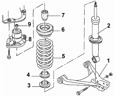
1 - lower arm, 2 - shock absorber, 3 - spring support, 4 - rubber spacer, 5 - spring, 6 - upper spring support with protective cover, 7 - buffer, 8 - upper support, 9 - self-locking nut, 25 Nm
The prevention Replacement of the shock absorber 2 is made assembled.
The rubber spacer 4 is installed on the spring support.
The upper spring support with a protective casing 6 consists of two parts.
When installing nut 9, a new nut must be used. Tightening torques for the rear suspension elements of an all-wheel drive vehicle Clamp for fixing the stabilizer to the rear beam 25 Nm Stabilizer to the lever 50 Nm Lever of the rear suspension to the fastening element of the hub 70 Nm + turn 90 ° Correctly fastening the shock absorber to the body 45 Nm Lower mount of the shock absorber to the lever 70 Nm + turn 90 ° back Brake caliper 30 Nm
Amortization strut repair
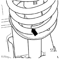
Correct positioning of the lower coil of the spring in the spring seat
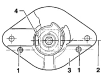
The location of the upper support of the shock absorber
1 - centering pins, 2 - axis of the lower rack fastening, 3 - upper rack fastening, 4 - lower rack fastening
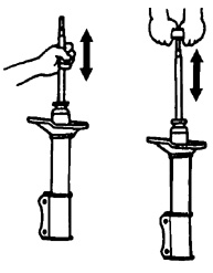
Checking the smooth movement of the shock absorber rod
The gas pressure in the new gas shock absorber reaches 25 bar, so when disposing of the gas shock absorber, be careful and wear protective goggles. There are two ways to dispose of the shock absorber: either by drilling a hole or by cutting the shock absorber body.
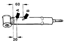
Drilling locations in the shock absorber housing
A - hole with a diameter of 3 mm, B - hole with a diameter of 6 mm
1. Fasten the shock absorber in a vise with the stem down. 2. Using a 3 mm drill, drill a hole in the shock absorber housing (A). The prevention When drilling a hole in the body of the gas-filled shock absorber, the gas under pressure will come out. Cover the hole with a rag when gas escapes from the shock absorber. 3. Continuing drilling, drill through the inner tube of the shock absorber (about 25 mm). 4. Using a 6mm drill bit, drill a second hole (B) in the body and inner tube of the shock absorber. 5. Install a suitable container under the shock absorber and, moving the shock absorber piston rod from stop to stop, squeeze out fluid from the shock absorber. 6. After draining the fluid from the shock absorber, the shock absorber can be recycled. Shock Absorber Cut
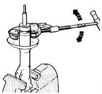
Fastening the shock absorber in a vice when cutting the shock absorber body
| Video (click to play). |
1. Fasten the shock absorber in a vertical position in a vise, see fig. Fastening the shock absorber in a vice when cutting the shock absorber body. 2. Install a pipe cutter on the top of the damper body and cut the damper body. In this case, gas will not escape from the gas-filled shock absorber. 3. Pull the damper rod up while holding the inner damper tube in the damper housing. 4. Remove the shock absorber rod from the inner tube. 5. Drain the shock absorber fluid into an appropriate container.

