In detail: do-it-yourself valve repair from a real master for the site my.housecope.com.
Gate valves made of cast iron, parallel, flanged with rising stem and manual drive
Discs 8 (Fig. 33) did not fully descend, did not press against the body o-rings
Tighten the handwheel 2 (Fig. 32) with a special wrench 8 or a pipe lever wrench 1. The ends of the spindle 4 and the nuts must be at the same height. Before tightening with the wrench, turn the handwheel back a few turns. This will ensure that the valve closes with less effort, since by extending the spindle, you can lubricate its threads.
Rice. 32. Opening and closing the valve: a, b - correct; c - wrong; 1 - lever pipe wrench; 2 - flywheel: 3 - scrap or pipe cuttings; 4 - spindle; 5 - stuffing box cover; 6 - housing cover; 7 - body; 8 - special key
The handwheel rotates, but the spindle is stationary
Rounded corners of convergence of the edges of the square on the spindle under the flywheel
Holding the spindle 13 (FIG. 33) with a pipe wrench, unscrew the nut 3 with any wrench and remove the flywheel 1. File the new edges lower than the existing ones with a file, if the length of the spindle allows. You can, by grasping the spindle with a pipe wrench, open and close the valve
Rice. 33. A gate valve made of cast iron, parallel, flanged with a rising stem and a manual drive: 1 - flywheel; 2 - running nut; 3 - nut; 4 - key; 5 - nut; 6 - stuffing box packing; 7 - gasket; 8 - disk; 9 - disk sealing ring: 10 - body sealing ring: 11 - wedge; 12 - case; 13 - spindle; 14 - housing cover; 15 - bolt; 16 - stuffing box cover
The flywheel rotates and the travel nut is stationary
Falling out or shearing off the key
| Video (click to play). |
Hold flywheel 1 with one pipe wrench, and unscrew nut 3. With the other, unscrew nut 3. After removing the flywheel, insert a new key 4 into the keyway into the keyway, made from a piece of steel wire or a nail filed with a file. The new key should fill the groove in the travel nut 2 and rest against the bottom of the flywheel keyway. This will prevent the key from falling out.
The handwheel rotates with the spindle and the valve cannot be opened for water passage
The rectangular end of the spindle inside the valve body is out of engagement with the discs
To lock such a bracket, two opposite grooves are drilled on the neck of one of the disks
The handwheel rotates with the spindle and it is impossible to use the valve
The corners of the spindle rectangle between the discs are rounded
The easiest way is to replace the spindle using an old valve that has become unusable for other reasons. You can also remove the spindle from a new valve, which will take less time than installing another valve.
We restore the worn out rectangular end of the spindle by shrinking, heating the spindle in a forge, or by surfacing using electric welding. After electric welding, the corners are corrected on a sharpening machine
The valve does not completely shut off the water despite the normal movement of the discs
Uneven build-up and scratches on the O-rings
After cleaning, rub one of the surfaces of the rings with chalk or wipe with the working side of an old carbon paper for a typewriter. Now wipe the contaminated surface on the corresponding mating surface. Regulate the formed colored bumps. Lapping is also not prohibited, but it is longer.
For coarse lapping, you can use the powder left over from the sharpener. You can also prepare a powder yourself from a mixture of finely crushed brick and glass.Spread the powder on a flat metal surface, on ceramic tiles, etc. Using the bronze sealing rings of the discs, drive through the mixture in different directions, sometimes lifting. In order for the mixture to envelop the surface of the rings better, add liquid oil to it, the mixture should acquire the consistency of a boot cream in boxes (the cream is thinner in tubes). Coarse lapping is also allowed with abrasive paper, glued or tied along the edges to the board. The width of the plank should be greater than the diameter of the ring. Rub the entire surface at once, changing the directions of the reciprocating movements and applying even pressure on the entire surface of the board. In this way, it is convenient to clean the surface of the disk, but it is difficult to clean the inner surface of the case when lapping, you can use special pastes such as GOI.
The flywheel is folded from the running nut
1. Grind a new nut on a lathe by creating edges on a milling machine or with a hacksaw and file. Note that the travel nut is almost always internally trapezoidal and externally metric. In valves D = 50mm, instead of a key, an external thread is cut on the travel nut 2. A flywheel is screwed onto it, which has a corresponding thread in the inner hole of the hub. The flywheel is countered with nut 3 (see Fig. 33). It should be noted that the threads on the running nut and flywheel are left-handed, that is, the flywheel will roll off the running nut if you tighten it, wanting to lower the discs and close the valve.
2. Remove the nut from a similar valve not installed in the pipelines. Rotate the nut clockwise. Reinstall the nut by screwing counterclockwise until it is seized with the threads of the flywheel hub.
3. Unscrew the flywheel. Putting a rag under the jaws of the pipe wrench, rotate the spindle by the upper threaded end in the desired direction.
Flywheel hub cannot be rotated
Broken wheel and flywheel spokes
Select the pipe wrench of the corresponding number on the hub or remove the hubs and work with the existing wrench. To grip cylindrical surfaces, the wrench must have two sharp-toothed jaws
Cannot open and close the valve
Putting a rag under the jaws of the pipe screw, rotate the spindle by the threaded end with it.
Leakage from under the stuffing box cover
Loose gland packing
Uniformly alternately tighten the nuts 3 on the bolts 15. If the flange of the gland cover 16 rested against the flange of the cover 14 of the body, then it is necessary to replenish the Packing 6 or remove the remnants of the old one and replace it with a new one. The gland can only be replaced by tightening the flywheel to the limit and checking how much the valve is closed. To do this, open one of the valves or taps located behind the valve. A slight leakage of water will not be a hindrance, but with a strong stream of water, stuffing the gland is prohibited, since the water will squeeze it out.
To stuff the stuffing box, unscrew the nuts 3 holding the stuffing box cover. Remove it from the housing cover 14. It is easier to do this if the gland cover is sequentially, or even better at the same time, pry off from both sides, for example, with a spade of a large screwdriver and a spudger or with the handles of the pipe wrench levers. To prevent the oil seal cover from interfering in the future, hang it on a wire from the flywheel spokes. Clean the exposed gland seat from dirt and scraps of old packing with a steel hook. After installing the first layer of fresh packing, try to tamp it well. It is most convenient to do this with the same stuffing box cover, if it enters freely
into the hole. When laying the sealing layers, half of the tube of a suitable diameter, cut lengthwise, will also help. It will be more convenient to use such a half of the tube if the handle is welded to it at an angle of 90 °. You can use as a handle sawn at an angle of 20-30 ° and bent sector: tubes.
Lower the stuffing box cover onto the recovered stuffing box and tighten with the nuts. The gap between the flange of this cover and the flange of the housing cover should remain 6-10mm as a reserve. Check the quality of your work by raising and lowering the spindle. A water leak will signal the need for further tightening of the nuts.
If there is no standard seal, use twisted burlap threads or cotton strips lightly oiled with any oil to prevent rotting. Suitable for sealing and natural fiber ropes. The oil seal can also be made up of specially cut rubber half rings, but in this case it is necessary to slightly tighten the oil seal cover. A strong tightening will lead to the emergence of excessive resistance to the movement of the spindle, and the rubber will crumble
Torn or squeezed gasket
As in the previous case, close the valve and check how much water does not pass through it. Then remove the connecting bolts between the cover 14 and the body 12 and after one time replace them with longer ones (longer by 20-25mm). Remove the remaining bolts too, and on long ones, unscrew the nuts 2-5 threads and immediately turn the flywheel towards the closing side. The cover 14 will rise slightly. Repeat the "procedure" until there is a gap of 1-15mm, sufficient to change the gasket 7. Sometimes the gap is increased in order to clean the surfaces from the remnants of the worn gasket.
Cut a new gasket along the old one or along the cover, reducing the outer dimensions by two bolt diameters. In one place, cut the gasket in a zigzag pattern to insert it into the gap between the cover and the body. The zigzag on the cut of the gasket must prevent water seepage. For security, two spacers can be fitted with a 180 ° incision offset. Leave the “horns” on the spacer to adjust the position of the spacer when cutting.
The best gasket material is rubber sheet, the worst is regular, non-corrugated oiled cardboard
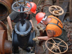
In addition, the valve may fail for other reasons. Therefore, in this article we will consider typical threats to the functionality of the device and how to eliminate them through periodic or overhaul of the valve.
The design of the valves assumes that during operation the unit may lose its functionality due to the following combination of circumstances:
- Loss of tightness in the body-pipeline docking unit.
- Loss of tightness in the spindle-stuffing box docking unit.
- Loss of tightness in the flap-body docking unit.
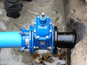
The cause of leaks between the valve body and the end of the pipe is either an assembly defect or a leak due to deformation of the sealing gasket that seals the joint. Diagnostics of such a breakdown is carried out visually: the need to repair valves - cast iron, steel or polymer - no difference, signals a leak in the area of the joint between the body and the pipeline.
The cause of internal leakage in the valve area is the use of valve valves in pipelines transporting a highly contaminated stream, the particles of which deform the sealing rings of the lock.In addition, particles can settle on the inner walls of the housing, thereby preventing intimate contact with the valve plug. It is very difficult to diagnose such a breakdown. After all, it is possible to identify internal malfunctions in the unit only by indirect signs - the presence of pressure surges in the blocked pipeline.
Gate valve repair technology depends on the type of failure. After all, external leaks (in the area of the body-pipe and the spindle-gland) are diagnosed and eliminated using completely different actions than internal leaks (in the area of the body-damper).
To maintain the level of maintainability of the line, it is very important to timely carry out all repair work in the valve assemblies. Otherwise, the cost of restoring valve valves will increase by several orders of magnitude.
The disassembly-assembly process is as follows:
- At the very beginning, the flywheel is dismantled, from which the running nut is removed.
- Further, the gland cover retaining screws are unscrewed from the housing cover. If the breakdown is associated with the spindle gland assembly, then after removing the cover, you just need to dismantle the gasket and replace it with a new, undamaged assembly.
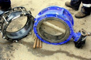
- After dismantling (and, if necessary, replacing) the stuffing box, it is necessary to disassemble the flange connection at the junction of the body and its cover. For this, the mounting screws of the cover are unscrewed from the mounting holes in the housing.
- After removing the cover, the spindle can be removed from the body and the valve can be pulled out of the seat. At this stage, you can clean the valve and body seat, along the way replacing the sealing elements. In addition, very often the valve is simply changed to a new part of the same shape. After all, all valve assemblies are standard, therefore, the locksmith cannot have problems with the selection of a workable element.
- Having replaced or restored the valve, you can proceed to the assembly of the valve, which is performed in the reverse order.
This operation can be carried out both on a disconnected valve and on fittings installed in the pipeline. But to replace the gaskets or eliminate errors at the junction of the body and the pipe, we will have to, without fail, dismantle the entire device, followed by disassembly-assembly and installation of fittings into the pipeline.
Upon completion of the repair work, the locksmith must test the device for operability. That is, the repaired valve must close the pipeline, completely stopping the flow of liquid in the pipeline.
The control device, in this case, is a conventional pressure gauge, which should record the pressure drop in the pipe located below (in the direction of flow) of the valve.
The main reason for the failure of the shut-off valves is the leakage of the sealing elements. The reasons for this may be:
- dirt caught under the sealing device;
- scratches, gouges, or uneven wear on the seal surfaces.
If a leak is detected in the valve, it is necessary to open and close it several times, allowing the flow of water to wash off the accumulated dirt from the seals. If this does not help, disassemble the valve or valve and remove the dirt from the sealing surfaces. In this case, you need to pay attention to the presence of scratches, sinks or dents and other irregularities on the surfaces, and, if necessary, eliminate them by lapping.
Lapping stop valves producing as follows. The sealing surfaces are lubricated with clean machine oil and sprinkled with emery dust or crushed glass. After that, the lap is evenly rotated along the lapped surface until the defects on the sealing surfaces are completely removed. At the end, a thin lapping is performed using a special paste. After that, the surfaces are wiped with clean rags soaked in kerosene, wiped dry and blown off with compressed air.
You can check the quality of lapping with oil or a pencil. One of the lapped surfaces is lubricated with mineral oil, applied to the other surface and, pressing slightly, turn to the right and left at an angle of no more than 20 ° 10-12 times. Then the surfaces are wiped dry and viewed into the light. With a high-quality lapping, the entire surface area should shine. If there are prominent shiny areas or streaks, then you should re-lapping with paste. When checking with a pencil, four radial lines are applied to the grated surface with a graphite pencil. With a good lapping, the pencil strokes must be erased over the entire surface over an area of at least 75%, otherwise the lapping should be repeated. The tightness of the sealing surfaces of the shut-off valves is carried out by a hydraulic test.
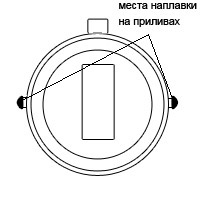 1. The valve is located on a horizontal pipeline and allows water to pass through in the closed position. In this case, the tides on the disks of the gates do not tightly touch the walls of the body, as a result of which the disks are displaced from the sealing surfaces of the body and form a gap between the disks and the valve body.
This malfunction can be eliminated by fusing the tides. Then the valve will work properly in any position.
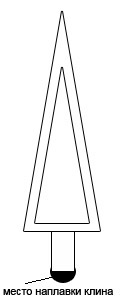
2. After long-term operation of the valves, the wedge does not expand the sealing surfaces sufficiently and the valve allows water to pass through in the closed position.
In this case, the wedge tail is lengthened by surfacing.
3. Falling bronze rings from discs or valve body.
Bronze rings are fitted to discs or to a groove in the body only when hot. When installing the old ring, you can additionally secure it with copper pins. In this case, under the rings you need to lay a thread of oiled asbestos packing, or lead wire, this will simplify the removal of old rings from the groove.
4. Falling of the gate disks due to the breakage of the steel clamp. In this case, it is impossible to open or close the valve.
When repairing this malfunction, it would be better to replace the steel clamp with a copper or brass one. In this case, fasten the discs to the spindle with a bolt.
5. Failure of the stuffing box cover is usually accompanied by water leakage from under the valve stem. To quickly eliminate water leakage without disassembling the valve, you can use a metal pad, which must be fixed over the damaged stuffing box cover.
6. A defective stuffing box will also cause water to leak through the stem. If this malfunction is not eliminated at the initial stage, then later it can lead to an emergency water leak, as well as create conditions for mechanical damage to the stem or stuffing box of the valve. Packing leakage can be due to the following reasons:
- violation of the cylindricality of the spindle;
- incorrect packing of packing in the stuffing box;
- wrong choice of packing material;
- Insufficient packing gland packing during laying.
Upon detection water leaks through the gland, the gland packing is tightened, here you should be careful, because the stuffing box cover is made of cast iron and can be damaged by excessive force. If it was not possible to eliminate the leakage by tightening the packing, the packing is replaced with a new one.The old packing is removed from the stuffing box, then the braided cord is cut into rings, along a length equal to the circumference of the spindle and placed in the chamber so that the joints of the packing are spaced out of alignment and overlap each other. The packing is finished by pressing the gland with a cover (gland follower). The stuffing box cover is clamped so that there is no distortion, and the depth in the stuffing box does not exceed 3-5 mm. In this case, the spindle should rotate easily without the use of special forces or levers. Gland packing on valves with a diameter of 15-40 mm can be made with a single cord, and for diameters of 50 mm or more it is necessary to cut it into pieces.
7. Breaks in cast iron valves. The reason for the ruptures is mainly the temperature elongation of the pipelines, which creates a stress in the metal of the gate valve in excess of the allowable one. Also, the cause of ruptures can be poor-quality cast iron casting, or freezing of water in them.
To prevent valve rupture, the following rules must be followed:
- Provide compensation for pipelines so that high stresses do not arise in the metal of the body.
- The flange bolts must be tightened evenly.
- Gate valves located on above-ground pipelines must be insulated.
- Protection of the valve from mechanical stress during storage and transportation.
The invention is intended for the repair of pipeline valves. A method for repairing gate valves, mainly wedge ones, by installing with a gap the finished seats in the body bores on a self-curing adhesive composition, followed by assembly and curing of the assembled adhesive composition. Before assembly, threads are cut in the body bores and on the seats. Each seat is made with an annular radial protrusion. Thereafter, the seats are screwed onto the self-curing adhesive composition into the threaded bores of the body. In this case, an elastically deformable element is installed between the annular radial projections of the seats or the ends of the seats and the body. This allows the screw-in seat to self-align along the wedge, and one resilient element provides a selection of all gaps, which increases the tightness of the connection between the seats and the body. This design reduces labor intensity and increases the reliability of valve repair. 3 ill.
The invention relates to the engineering industry, in particular to the repair of pipeline fittings.
A known method of restoring the sealing fields of the gate, which consists in surfacing a hard stainless alloy directly on the body and wedge of reinforcement, followed by machining and lapping (see AF Pongilskiy. Fitter for the repair of pipelines and steam-water fittings. M .: Higher school, 1973). This method is rather laborious and requires special, precise and complex equipment.
There is also known a method of repairing wedge valves (see AS 310078), which consists in installing in a gap in the bore grooves of the body and wedge, for example, metal rings on a self-curing composition, followed by assembly of the wedge and body, holding the assembly until the composition cures ... The disadvantages of this method include the possibility of incomplete adhesion of the sealing rings of the body and the wedge to each other (and hence the lack of tightness) and the impossibility of self-installation in the absence of a lateral gap between the ring and the groove. And if these gaps are sufficient for self-installation of the rings, it is possible to squeeze out the self-curing composition before its polymerization, which means that there is no elastic pressing of the rings to each other, which also leads to a loss of tightness or the appearance of incomplete contact of the rings with the adhesive composition, which reduces the reliability of the connection. Moreover, this method is not applicable to gate valves with screw-in seats (see DF Gurevich. Calculation and design of pipeline fittings. L .: Mashinostroenie, 1969, Fig. 129-131).
The objective of the invention is to reduce labor intensity and improve the reliability of repair.
The technical result is achieved by the fact that the sealing fields of the wedge and screw-in seats are mechanically processed "as clean", i.e. with the removal of the minimum allowance until the traces of wear disappear, the sealing fields of both the body seats and the wedge are lapped, the threads are cut on the seats in the body bores, and then screwed onto the adhesive self-curing composition into the threaded bores of the body, while between the annular radial protrusions of the seats or with the ends of the seats and the body, an elastically deformable element is installed.
The essence of the invention is illustrated by drawings: FIG. 1 shows a wedge gate valve with screw-in seats in section, FIG. 2 - view A in Fig. 1, variant, in FIG. 3 - view A in FIG. 1, option.
In the body 1, seats 3 are installed on the thread 2 with a gap 4, in which a self-curing composition 5 is placed, limited by an elastically deformable element 6 or 7, installed between the body 1 and the annular radial protrusion 8 or the end 9 of the screw-in seat 3, the sealing field 10 of which interacts with the sealing field 11 of wedge 12.
After disassembling, the saddle 3 is cleaned of dirt, the sealing fields are treated “as cleanly” and rubbed in, the thread of the saddle and the body bores are cut or the existing thread is loosened with a gap sufficient for self-installation, then the sealing fields 11 of the wedge 12 are also treated “as cleanly” and rubbed in their. After that, the thread of the seat 3 is covered with a self-curing composition 5, elastically deformable elements 6 or 7 are installed and the seat 3 is screwed into the body 1, then the wedge 12 is inserted into the body 1, taking into account the overlap of the sealing fields of the wedge and the seat, ensuring the tightness of the product, and left assembled until self-affirmation. The valve is ready for operation.
Depending on the degree of wear of the sealing fields of the seats 10 and the wedge 11, one or two seats are installed on the elastic element 6.
Thus, the minimum machining “as clean”, lapping four fields, threading - such is the volume of machining of the proposed method, which is much less than the known analogs. Mating clearances allow the screw-in seat to self-align with the wedge, and one elastically deformable element allows you to select all the clearances in the seals.
A method of repairing gate valves, mainly wedge ones, by installing, with a gap, the finished saddles in the body bores on a self-curing adhesive composition, followed by assembly and curing of the assembled adhesive composition, characterized in that before assembly, threads are cut in the body bores and on the seats, and each saddle is made with an annular radial protrusion, after that the seats are screwed onto the self-curing adhesive composition into the threaded bores of the body, while an elastically deformable element is installed between the annular radial protrusions of the seats or the ends of the seats and the body.
The need to service the valve is its main disadvantage, but the possibility of repair is one of the main advantages.
Leaky flow shut-off
Defects in the contact surfaces of the valve and body. (scale, sinks, scratches)
Lapping of sealing surfaces on the valve and in the body. As a rule, the contact surfaces are made of bronze. To do this, it is necessary to dismantle the cover, remove the shutter, and, if necessary, the body. Grinding is performed with diamond pastes of various grain sizes with a gradual transition from coarse to fine.
It should be borne in mind that in wedge valves, after several lapping, the valve sinks, which leads to a leakage even with polished wedge surfaces.
Leakage from under the stuffing box along the stem
Tighten the stuffing boxes, and if necessary replace the stuffing box packing.
If, after replacing the stuffing box, the leak could not be eliminated, most likely corrosion pits have formed in the stem and it will have to be welded or replaced.
The flywheel cannot be turned
Occurs in valves devoid of attention from the maintenance personnel and open less than once a year. The reason is limescale on the sealing surfaces.
Remove the valve top cover and clean the disc and body sealing surfaces. If necessary, lapping the rubbing surfaces.
Do not knock on the stem, as the guide nut may be ripped off.
Handwheel turns but valve does not open
Opening the shutter "cheeks fell"
In rising stem valves, this problem occurs when the “cam” of the stem retaining the valve is worn or if the threads on the stem guide nut have been stripped.
If there is a problem with the stem, replace it or weld on a worn “cam.”.
A worn guide nut should be replaced if the valve design allows it.
In valves with a non-displacement stem, the valve may fall when the nut fixed in it wears out. To eliminate the malfunction, it is necessary to replace the valve, since it is most likely that it will not be possible to replace a nut with a stripped thread.
Do not disassemble the valve while it is under pressure.
After installation, it is necessary to remove air from the valve; for this, the bolts pressing the gland are loosened, and after the appearance of water drops from under the gland, the bolts are pressed.
Once a month, perform a full cycle, open / close, to clean rubbing surfaces from a small layer of accumulated scale or sludge.
Keep the stem of rising stem valves lubricated.
Check the stem packing for leaks once a week and retighten or replace it if necessary. It is not allowed to replace the stuffing box on a pipeline under pressure.
The gate valve must not be in an intermediate position during operation. Either fully open or fully closed valve position is allowed.
Pipeline fittings are used by enterprises in the energy industry, housing and communal organizations, in the metallurgical, chemical, food and other industries.
Table of varieties and classifications of valves for the pipeline.
Shut-off, phase-separation, protective, distribution, high-pressure, shut-off and control and control valves act on the flow area, determine changes in the flow of substances, actually control them. The task of the valves is to start and stop the flow of the working medium. Timely diagnostics and high-quality repair of valves ensure efficient operation of the whole system, reliable fixation of the extreme positions of the unit ("closed", "open").
The movement of the flow of gas, vapor or liquid is regulated by the most common type of shut-off valves - a gate valve. You can conditionally classify devices according to several characteristics.
By type, valves are distinguished:
The seating surfaces of the parallel gate valve are parallel to each other.
According to the shape of the shutter, valve valves are distinguished:
A feature of wedge valves is the stopping of the movement of the flow of substances by translational rotation of the gate perpendicular to the main flow of the transported substance. The sealing surfaces of the wedge gate are located at a certain angle in relation to each other. All types of wedges are made of high-alloy steel. Application - transportation of ammonia (liquid and gaseous), steam and water, non-aggressive oil products.
The seating surfaces of the parallel gate valve are parallel to each other.Distinguish between single-disc (gate) and double-disc valves.
By the type of movement of the spindle, there are valves:
- with a rotating spindle (translational-rotational and translational movements);
- with rising stem and spindle (rotary movements only).
Rotary stem valves are used in pipelines where frictional lubrication of the nut and spindle is required and there is no threat of component corrosion. Gate valves with a rising stem are higher than rotating ones, due to their technical characteristics they are used in all other systems.
A cast iron valve is used to start and completely stop the flow of substances. The maximum operating temperature is 225 ° C.
By the type of material, valves are distinguished:
A steel gate valve blocks movement in the pipeline. Permitted working substances - steam, water, non-aggressive oil products in gaseous and liquid form. They are used to work with different pressure levels and passages in temperate climates along the entire length of the pipeline.
A cast iron valve is used to start and completely stop the flow of substances. The maximum operating temperature is 225 ° C. Permitted substances - steam, oil products, oil, water. Installation on horizontal and vertical pipelines is allowed, taking into account the peculiarities of installation.
Both types of valves belong to the category of repaired valves with forced service life.
Separately, a pinch valve is distinguished, which consists of an elastic pipe placed in a protective housing flanged on the flanges. There is no contact with the working medium at all. The principle of operation is one-sided or two-sided closing of the elastic hose (pinching). Application - transportation of abrasive slurries, oil products, sludge, aggressive substances. The temperature of the medium should not exceed 110 ° С, and the pressure in the pipeline should not exceed 6 kgf / cm 2.
Installation and maintenance of devices must be carried out by highly qualified specialists.
The use of valve valves in technological and transport pipelines at key and auxiliary enterprises of various types of industry, in energy systems, in gas, oil and water pipelines is due to the following technical characteristics:
- long service life under adverse conditions;
- low hydraulic resistance;
- resistance to significant loads.
Installation and maintenance of devices should be carried out by highly qualified specialists with a sufficient level of knowledge, admission to carrying out a specific operation, and having the skills to use a specific type of valves.
The main reason for the valve malfunction is damage to the surface of the sealing rings due to the ingress of foreign small particles (sand, scale, etc.), while the tightness of the structure is broken, the transported substance leaks. In addition to significant material losses, when transporting hazardous or corrosive substances through a pipeline with faulty units, damage to the environment is possible, and in the most difficult situations, the life of workers involved in the process is at risk.
At the end of the work, specialists test the assemblies for the tightness of the seals, test the operability of the device.
Timely diagnostics and repair of the technical condition of the unit affects the quality and efficiency of the system.
To eliminate faults, depending on the location of the damaged unit, observing safety rules, the valves are disassembled, and at the end of the work they are assembled with a standard tool in specially equipped workshops or directly in the pipeline system. The employee responsible for the work is obliged to ensure adequate protection of the threaded and sealing elements from damage, to prevent the ingress of foreign particles into the cavity of the unit.At the end of the work, specialists test the assemblies for the tightness of the seals, the valve, the gasket, and test the operability of the device.
Repair and dismantling of valve valves is prohibited if:
- there is pressure in the valve cavity or system;
- the medium remains in the device.
It is unacceptable to use knots to regulate the flow.

