In detail: do-it-yourself phone charging repair from a real master for the site my.housecope.com.
Now, as never before, the number of gadgets per person has reached the maximum value.
Phones, tablets, laptops, various wireless headsets - all this abundance of technology has a power source and, accordingly, a charger for it.
Chargers are often carried with them in a bag or pocket, and so that they take up a minimum of space, their cords are twisted with a bend and a stretch.
This, in turn, leads to an almost imperceptible wire break and inoperability of charging. Just break in the cord - this is the most common breakdown in such types of devices, and, frankly, it is a pity to throw it away because of this.
Yes, you can certainly buy a new one and not suffer, but if the device is non-standard, for example, an old model phone, then it is not always possible to find such a charger. And at the "flea market" you can slip a block with the same problem, and no one needs extra spending.
Therefore, repairing a charger is a useful and worthwhile business.
Below, in this article, a simple repair method that does not require special equipment will be described, which will give your charge a second life.
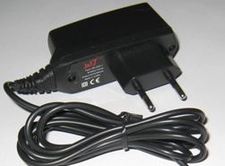
In the photo - charging with a problem in the cord.
The cliff is not always visible to the naked eye. It can be hidden under the thickness of the main (top) insulation and remains practically invisible.
But, as practice shows, the fracture occurs most often near the entrance to the block or at the base of the plug.
To locate the break, just connect the included charger to the phone and wiggle the cord in a suspicious place.
As soon as you see that the charging "went" for a moment, it means that there is a break in the place where you were moving at that moment.
| Video (click to play). |
In this case, looking closely, the break and cliff were visible even without stirring. It just turned out at the entrance to the power supply.
The main problem in the repair of such blocks is that it is not collapsible. Therefore, to get to the electronic board, you need to be careful and some effort.
Using a screwdriver and a knife, pry off the base of the rear cover and remove it.
Pry should be at the point where the cord enters the device. If the entry is too tight, you can cut the rubber strap slightly.
This must be done carefully so as not to cut the wire at all.
Having poked it up with a screwdriver, we try to lift the cover up.
It may happen that it cracks in half, but more often, as in this case, the cover was removed entirely, without damage.
It was even seen that it had latches, and in the charger case there were recesses for them.
This means that it is possible, after repair, to put the cover in its place without using glue.
When the cover is removed, you need to pull the printed circuit board out of the case. Since it "sits" tightly, a screwdriver will help to get it out. Leaning the blade of the screwdriver against the body and hooking it with the end of one of the soldering points, we pull the board out.
The structure of the case is such that when the board is inserted inside, its input contacts are connected to the clamps of the pins of the power plug. Therefore, when installing the board back into the case, you need to take this point into account.
The photo below shows the board with all its "insides". The wires are soldered at the bottom.
View from the opposite side.
And here in the photo are the tracks for the input contacts.
The wire will have to be cut below where the damage is. But it is very important to remember which wire is "+" and which is "-". In some cases, the wires are colored accordingly, red is the positive and black is the negative.
With color marking, you can safely cut, and then just solder the wires, observing the polarity.
In our case, the wires are of the same color, but since the cord is flat, you can trace from which side of the cord the wire goes to minus, and from which to plus. Mark and then crop.
Next, unsolder the remaining ends from the board and prepare holes for soldering a new wire.
Without losing the label, strip and tin the wires on the cord.
Solder them one by one to the board, observing the polarity.
The PCB usually has polarity markings at the soldering point.
To prevent the cord from dangling at the outlet, we wind a bandage of black electrical tape around its entrance part. The thickness of the band should be such that it fits into the slot for the wire and locks into it.
Before installing the cover, we check the operation of the device. We plug it into the network and connect it to the phone. If the phone is not with you at the moment, we use a DC voltmeter.
Since the internal contact in the socket has a very thin tube, and the probe of the device does not go into it, you can use a piece of thin copper wire to check.
Having inserted it into the tube of the internal contact, we connect the probes of the measuring device to it and to the external output of the plug.
The voltmeter shows that voltage is present, which means that the breakdown has been repaired.
Now we snap on the back cover.
We connect the phone and rejoice at the results of the work done.
The most common reason for the failure of a charger is a careless attitude towards it during operation.
Phone charger repair
Possible causes of breakdowns of the mobile phone charging unit
1. Broken wire at the plug and at the base of the charging unit. You can break the wires when the charger is on during calls.
You need to pull the plug out of the phone jack not by the wire, but by the plug body.
2. Failure of the elements of the electronic board of the charger. Very often, the charger is left plugged in and is not removed from the outlet. In this case, the entire electronic board of the charger is constantly energized, which reduces the service life of the radio elements of the board.
The wrong order of switching on and off the charger also leads to premature wear of the elements of the block.
If the phone is disconnected from the charger while energized, sudden voltage surges occur that exceed the maximum permissible operating voltage of the cells. This is due to transient processes that occur in the memory when the load is removed (disconnecting the phone) under voltage. With proper operation of the charger, the phone is connected and disconnected with the charger turned off.
You don't need to be a great specialist to find and fix a broken wire from the charging unit to the plug. Wire breakage can be detected when the phone is connected. Having connected the phone to the charger, bend the wire at the plug u of the base of the unit, while simultaneously observing the continuity of the battery charging process.
In these places, wire breaks most often occur. If a break is found at the very base of the plug, then the wire is cut off at a distance of 5-7 mm from the plug. This is necessary in order to be able to solder the whole part of the wire. The soldered wires are insulated separately with a thin heat-shrinkable tube.
When the soldering points of the wires are insulated, a thicker heat shrink tube is put on the plug to stiffen the soldering point. Sometimes a wire break occurs at the very base of the plug, then the plug is completely freed from the plastic seal, and the wires are soldered directly to the plug.
Do not reverse the polarity of the plug wires. The break point is also found with a multimeter in the audible dial mode or visually. The found place of wire breakage is cut with a small margin on both sides. Peel the top insulation off the wire. Then it is cut off, stripped of insulation, twisted and soldered, after putting a thin heat-shrinkable tube on each wire, and a thicker tube on the common wire.
After soldering, they put thin tubes on the wires and upset them, heating them with a soldering iron.At the end, a thicker tube is put on in place of the upset thin tubes so that the thick tube overlaps them in length. When soldering wires, observe the polarity according to their color. You can purchase a new cord with a plug for your brand of phone from specialized stores. Then phone repair comes down to a simple replacement of the faulty wire.
The type of faulty capacitors
Another common malfunction of a phone charger is a loose contact between the pins of the power plug. The spring-loaded pins of the mains plug often extend from the contact pads on the PCB. To eliminate such a malfunction, it is enough to bend these contacts inside the block.
Open the cover of the block. It is good if there are screws securing the charger cover, and if they are soldered. In this case, you need to cut a slot along the entire perimeter of the cover with a hacksaw blade with fine teeth. Having eliminated the malfunction, the lid is closed and fixed with tape 1 cm wide.
More complex, but quite affordable for an electrician are device breakdowns associated with the repair of elements of the phone charger board. First of all, they open the memory and take out the board. Repair begins with a visual inspection of the elements of the printed circuit board and the condition of its tracks.
Pulse charger circuit for phone
When inspecting the elements, pay attention to the swelling of the upper part of the capacitors, darkening and violation of the integrity of the resistors. Darkening of the resistors and the tracks below it indicates that the operating temperature has been exceeded. In this case, the resistor itself is checked for resistance and the diodes and transistors are ringed.
The pinout of the transistors and the memory circuit for your phone brand can be found on the Internet. If it was not possible to visually detect a malfunction, turn on the device and measure the input mains voltage. If the mains voltage is present and a faint sound of the pulse transformer is heard, then the output voltage of the unit is measured.
It should be within 7.5V no load. If there is no output voltage, and the transformer is buzzing, then you need to look at the resistance of the output winding of the transformer and the elements that follow it. Since the charger of mobile phones is assembled according to a pulse circuit, when repairing them, you can focus on the article "Repairing a switching power supply with your own hands."
Greetings radio amateurs.
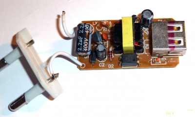
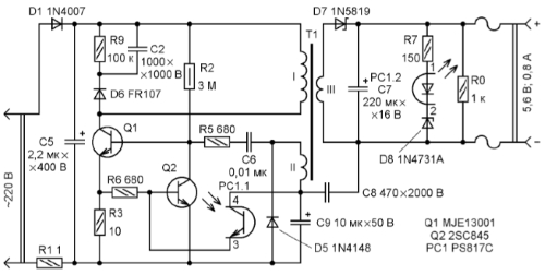
Going through old boards I came across a couple of switching power supplies from mobile phones and wanted to restore them and at the same time tell you about their most frequent breakdowns and elimination of shortcomings. The photo shows two universal schemes of such charges, which are most often found:
In my case, the board was similar to the first circuit, but without an LED at the output, which only plays the role of an indicator of the presence of voltage at the output of the block. First of all, you need to deal with the breakdown, below in the photo I outline the details which most often fail:
And we will check all the necessary details using a conventional DT9208A multimeter.
It has everything you need for this. Continuity mode for diodes and transistor transitions, as well as an ohmmeter and capacitor capacitance meter up to 200μF. This set of functions is more than enough.
When checking radio components, you need to know the base of all parts of transistors and diodes, especially:
Now we are completely ready to check and repair the switching power supply unit. Let's start checking the unit to identify visible damage, in my case there were two burnt resistors with cracks on the case. I did not reveal any more obvious shortcomings; in other power supplies I met swollen capacitors, which also need to be paid attention to in the first place. Some details can be checked without soldering, but if in doubt, it is better to unsolder and check separately from the circuit. Solder carefully so as not to damage the tracks. It is convenient to use a third hand during the soldering process:
After checking and replacing all faulty parts, do the first turn on through a light bulb, I made a special stand for this:
We turn on the charger through the light bulb, if everything works, then we twist it into the case and rejoice at the work done, if we are not looking for other disadvantages, also after soldering, do not forget to wash off the flux, for example, with alcohol. If all else fails and nerves are in the balance, discard the board or solder and select live parts in stock. Everyone is in a good mood. I also suggest watching the video.
JLCPCB is the largest PCB prototype factory in China. For more than 200,000 customers worldwide, we place over 8,000 online orders for prototypes and small batches of printed circuit boards every day!
Or sign in with these services
Register to get an account. It's simple!
Good evening, dear blog readers! For a long time I had a charger for my LG phone, which actually charged me a bunch of other devices. But at one point, I noticed that the phone was not charging as expected. Either the phone is charging, then no, the charging status could change once a second. I put it aside for a long time, bought a new charger, but still the question of how to fix the charger for the phone arose and itched))).
The charger for the phone was composite - a usb wire was inserted into the plug, which in turn was stuck into the phone. There could be two reasons for the inoperability of charging:
- broken usb wire
- malfunction in the plug itself
The first option is easy to check - just replace the wire itself, I’ll say right away that it didn’t help, otherwise there would probably be no point in writing a whole article about it.
There was a fault in the plug ...
In order to find the malfunction and eliminate it, it was necessary to open such a plug. Above it is crowned with gray plastic, which is well glued to the white body of this fork. Of course, if my task were not to fix the Just for fun charger, but to preserve it for future generations for future use, then I would be very confused. But I barbarously broke off the gray top and took out the inner board with pliers.
Quite an ordinary handkerchief from usb-charging the phone. The low-voltage part, the PWM environment and the part where the contacts for connecting to 220 V with a diode bridge and resistance are located are separately highlighted.
Because charging periodically still worked, logic dictated that the contacts in the plug itself were simply leaving. We draw your attention to these contacts:
In turn, the plastic case, where the pins of the plug are attached, also have their own contacts:
Cleaning them, lifting them slightly, as well as wiping the contacts on the side of the board with an eraser solved the problem - after assembly, the charging worked as it should.
If the following cosmetic actions did not help, then you would have to dig deeper. I had to check again if the capacitor was swollen, such a large one, located next to the 220 V contacts on the board. It would also be necessary to "inspect" the input resistance, which acts as a fuse (green thing with stripes in the photo above). Judging by my measurements with a multimeter and by the markings on the "belly" of the resistance, its rating in this charge was 10 ohms. If it burns out, it would need to be re-soldered, but this would indicate a problem in the circuit. That is, it would be masking the problem.
Also, one of the problem areas in charging is the transistor, it often burns out.
Just in case, I give a link to one useful video. In it, the author talks in detail about the problem that arose with a similar charge:
In the process of working on this post, I needed to edit a video, which I, however, did not upload. If there is a need to trim videos, insert simple titles, then there is little point in resorting to some paid products, everything is already in Windows - this is Windows Movie Maker.But as soon as it is necessary to do something more, for example, to enlarge the video, then this program is already not enough. I liked Movavi Video Editor, which combines a number of useful features - it's powerful enough, easy to learn, and cheap. I appreciated her and even acquired... It allows you to easily apply special effects, hide on the video something that you don't want to show (wallet numbers, phones, etc.), stabilize the video, and a whole bunch of other things. Later I will make a small review of it.
Thanks to! You have successfully subscribed to new blog content!
Perhaps the most "sick" part of a cell phone is its charger. A compact DC power supply with an unstable voltage of 5-6V often fails for various reasons, from the actual malfunction to mechanical failure as a result of careless handling.

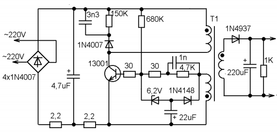
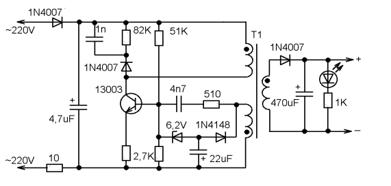

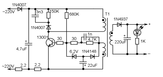

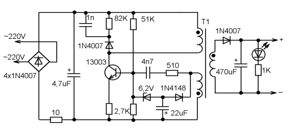
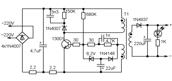

So, what are the "typical" malfunctions? First of all, you should pay attention to the capacitors. A breakdown of the capacitor connected after the mains rectifier is very likely, and leads both to damage to the rectifier and to the burnout of a low-resistance constant resistor connected between the rectifier and the negative plate of this capacitor. This resistor, by the way, works almost like a fuse.
Often the transistor itself fails. Usually there is a high voltage power transistor marked "13001" or "13003". As practice shows, in the absence of such a replacement, you can use the domestic KT940A, which was widely used in the output stages of video amplifiers of old domestic TVs.
Breakdown of the 22 μF capacitor leads to the lack of generation start. And damage to the 6.2V zener diode leads to an unpredictable output voltage and even failure of the transistor due to overvoltage at the base.
Damage to the capacitor at the output of the secondary rectifier is the least common.
The design of the charger body is non-separable. You need to saw, break: and then somehow glue it all together, wrap it up with electrical tape. The question arises as to the expediency of the repair. After all, to charge a cell phone battery, almost any constant current source with a voltage of 5-6V, with a maximum current of at least 300mA, is enough. Take such a power supply and connect it to the cable from the faulty charger through a 10-20 ohm resistor. And that's all. The main thing is not to mix up the polarity. If the connector is USB or a universal 4-pin, connect a resistance of about 10-100 kilohms between the middle contacts (select so that the phone "recognizes" the charger).
- failure of the charger unit;
- violation of the contact connection of the wire with the plug or charger unit.
Very often, the reason for the failure of the charger is a wire break or a breakdown in the contact of the wire with the structural elements of the charger - the plug and the block.In this case, you can repair the charger yourself. Let's consider the principle of repairing a damaged charger wire using a specific example of repairing a Nokia mobile phone charger (with a thin plug).
To repair the charger, we need:
- soldering iron and everything you need for soldering;
- insulating tape and heat shrink tubing (if available);
- a small piece of thin wire to make contact with the inner contact part of the charger plug (for Nokia charger slim plug).
The first step is to find a damaged wire or contact connection. Wire damage can be identified visually. The place where the conductive core ruptured, as a rule, is of a different color and slightly smaller in diameter.
If by visual inspection it was not possible to determine the places of damage to the wire, then, most likely, the charger does not work due to the wire breaking off at the point of its connection to the block or plug. The wire may also be damaged, we will find out in the process of further finding the damage.
We take the wire and cut it 7-10 centimeters further than the plug. If there is no breakdown of contact at the point of attachment to the plug, we will connect the wire at the cut. Therefore, you cannot cut the wire at the point of connection to the plug, that is, you must leave a small piece to be able to connect the wires by soldering.
Strip the wires from the part of the wire that goes to the charger. Take a multimeter and select a DC voltage measurement limit of 20 volts. Connect the charger to the network and measure the voltage value at the charger output, that is, at the stripped ends of the cord.
We measure the voltage at the output of the charger
If the device shows a voltage value, then this indicates that the charger unit and the wire are not damaged. In this case, the device showed 7 volts - this is the nominal output voltage of this charger. At this stage, we can conclude that the charger does not work due to a breakdown of the contact of the conductors at the point of their connection to the plug. You can verify this by ringing the plug with the device.
To do this, we strip the wires that go from the plug, insert a thin wire into the inside of the plug (this is necessary for contact with the inner contact part of the plug).
We take a multimeter and select the dialing mode. With one probe, we touch one of the stripped conductors, and with the other, first, to the outer contact part of the plug, and then to the inserted wire. If the device showed contact (the presence of a sound signal), then this indicates that the contact between this wire and the plug is not broken.
We rearrange the probe of the device to another stripped conductor, with the other, alternately touch the outer part of the plug, and then to the wire. If, when both contact parts of the plug are touched, the device does not emit a signal, then there is no contact. That is, one of the wires is torn off the plug.
In this case, there are two ways: you can buy a new plug, or you can repair the old one. The first method is simpler and more reliable. A new plug can be purchased from mobile phone repair shops or the radio market. You may have an old charger that does not have a damaged plug.
In this case, it is enough to solder the new plug to the charger, while observing the polarity. How to check if the wires are connected correctly (polarity)? Typically, each cord has a color-coded wire. If it does not match, then you need to make sure that the wires are connected correctly.
To do this, plug the charger into a wall socket and the new plug into your mobile phone. Connect the conductors of the plug to the charger cord. If charging has started, then you have connected the conductors correctly. If the phone does not charge, swap the conductors.The check must be carried out in any case, even if the color coding of the cords to be connected is the same, since there may be a discrepancy in the cords marking.
The next step is to solder the two cords together. If you have a heat shrink tubing, place a portion of it over one of the cords to be soldered before soldering. Solder the conductors observing polarity. Insulate both wires with insulating tape, put on heat shrink tubing. Check the charger is working properly.
If you do not have the opportunity to purchase a new plug, and you still want to reanimate the charger, then the second way to eliminate the damage is suitable for you - repairing the plug.
Remove the rubber (plastic) cover from the plug with a knife. In this case, be careful, do not rush, as you can damage the plug itself.
Remove the rubber cover from the plug
The next step is to solder the charger cable to the plug.
Soldered cord to plug
We check the performance of the charger. If everything is normal, we insulate the conductors and put a heat-shrink tube on the plug. The charger is now ready for use.
Heat shrink tubing on the plug
We examined the case of a broken contact at the point where the cord was connected to the plug. There may also be another reason. Let's consider one more case.
You cut the wire, checked for the presence of voltage at the output of the charger, it is absent. We cut the wire near the charger, stepping back from the charger block 7-10 cm. We clean the wire that comes out of the charger block and check for the presence of voltage at the output. The presence of voltage at the output indicates that the charger is working properly. We call the plug using the above method. In this case, there is no breakdown of contact.
The dialing of the charger cable showed that one of the conductors was cut off. No damage is visible visually. The best option is to purchase a new wire. Then solder it to the plug and the charger block, observing the polarity.
In order not to be mistaken (especially if the wires have the same color marking), before soldering the wires, connect them and plug the charger plug into the phone. If charging has gone, connect the conductors with soldering. Insulate the wires at the soldering point and put on a heat-shrinkable tube (it must be put on the wire before soldering). The damage has been repaired.
If the wire is intact, the contact connection of the plug is not broken, then the charger unit is damaged or one of the wires inside the unit is torn off.
Unscrew the charger box and look at the wire connections. If all the wires are connected normally, then the charger unit itself is damaged.
If you have a damaged charger unit, then, without having skills in electrical engineering, you will not be able to find the cause of its failure, and even more so to fix it yourself. Repairing your charger from a specialist service will cost you more than a new charger.
Very often, equipment breakdowns are so elementary and easily removable that sometimes you don't even want to take on repairs, it is not of interest, but you have to. Recently, a friend of mine turned to me for help, who had not lived well before, and recently, due to the crisis, has also lost his job.
Shows universal charger type Frog for lithium batteries from phones, with the fasteners of the pressing part broken off, and asks if anything can be done. Says that they sat on it. The first thought was to offer him to throw it away and buy a new one, but after looking at his face upset by the breakdown, he changed his mind and decided to help.
There were two new crocodiles in isolation, only the tip protruded, and it was decided to solder to the wires going to the antennae, and to connect to the battery with crocodiles. I plugged the charger into an outlet to make sure that it works at all, and my labors will not be in vain, and began to disassemble.
First, 2 screws were unscrewed, fastening the antennae to the part holding the battery, the antennae were intact. Often, during work, these antennae break off, and it becomes impossible to use, so he left the antennae in reserve. If someone does not know how to use such a charger, I will explain: we take a lithium-ion battery from a cell phone, camera and other similar equipment. We combine the antennae of the charger, with its plus and minus contacts, they are signed on the battery, and we press the battery to the charger body, due to the spring of the pressing part. The LED on the charger should light up, indicating that there is contact between the antennae and the battery contacts. For those who may need to send a similar charger, with a more serious breakdown, I will give one of the options for the circuit diagram:
Let's go back to our repair, having unscrewed two screws, disassembled the frog's body. It remained to determine which of these wires going to the antennae is plus and which is minus. Such a check is rather arbitrary, because on such chargers there is either automatic polarity detection, and then there are no buttons, or there is a polarity reversal button.
But all the same, I wanted to assemble so that the red probe was a plus, and the black one was a minus. Then I took off the board and found a common wire connected to one of the wires, it was connected to a polygon on the board. It was decided to count it as a minus. Further a matter of technology, beautiful wires were needed to connect with the wires coming from the antennae. I just had such wiring from a computer speaker. The speaker itself and the connector were cut off, I decided to take the length of the wires long enough for easy connection to the battery contacts.
Recently, I have gotten into the habit of following the aesthetics of connections in the device, it doesn't matter if I'm doing it to myself or to people, for money or for purely symbolic gratitude. Therefore, I bought myself heat shrinks with a margin, of different diameters, for all occasions, and decided to abandon the snot on the joints in the form of electrical tape. Which, by the way, not only does it look ugly, but also strives over time to crawl off the wire connection and expose it. What this is fraught with, I think nobody needs to explain.
So here, too, before soldering the wires, I put two pieces of heat shrink on the wires, and after soldering I warmed up the lighters on the fire. The result is a beautiful, reliable insulation. By the way, in the West, judging by the insulation of LEDs and buttons, computer cases, they have long abandoned the use of electrical tape, and pack everything that remains for long-term use only in heat shrinkage. Before soldering the wires, out of habit, I tied the wires in a knot so that it would be impossible to forcefully pull the wires out. To do this, just a node, the size of which is larger than the hole into which the wire in the charger case is passed, will not allow.
It remains only to assemble the charger in the case and test it by plugging it in and connecting it with the crocodiles to the battery contacts. Everything worked as it should, the LED began to blink, indicating that the battery is charging. And as it turned out, with the polarity and color of the crocodiles, when soldering the wires, I was not mistaken. Successful repairs to everyone! The author of the article is AKV.
With the increase in the mobile phone fleet, the number of chargers supplied with phones is proportionally growing. Given the poor quality of our power grids, these devices often fail. This is especially true for models of chargers from unknown manufacturers, purchased on radio markets due to their low cost.
As a rule, to maintain profitability, such manufacturers use cheaper components in their devices, which inevitably entails a decrease in their reliability.
After, after not working for a week, a similar charger for the NOKIA phone bought on the radio market failed, it was decided to find out the cause of the malfunction and make the necessary changes to the circuit to improve the reliability of the device as a whole.
It should be noted that comparing two chargers - certified and "gray", the difference is not easy to find (Fig. 1). The body of the device of an unknown manufacturer (above in Fig. 1) is distinguished by a less deep embossing of the NOKIA logo and technical characteristics of the device, as well as the absence of a silk-screened icon that regulates the method of disposal of the device at the end of its service life. In fig. 2 shows the circuit board of the device.
The schematic diagram of the device has been restored from the circuit board. It is a classic reverse pulse converter (Fig. 3).
Such simple circuits are widely used in switching power supplies and chargers (up to 25 W).
The declared characteristics of the device are an output voltage of 5.7 V and a load current of 800 mA.
And now we will briefly consider the principle of operation of the power supply in a schematic diagram (Fig. 3).
The mains voltage is fed through the current-limiting resistor R1 to the input of the rectifier on diodes D1-D4. The transistor Q1 has an oscillator, the frequency of which is mainly determined by the characteristics of the pulse transformer TF1 used here. Resistor R3 sets the operating mode of transistor Q1. The stabilization of the output voltage occurs through the use of the feedback winding of the pulse transformer TF1 and the D7 C4 ZD1 circuit. Transistor Q2 and resistor R2 serve to limit the current of transistor Q1 at the time of starting the oscillator, as well as in the event of an overload or short circuit at the output of the device. The circuit contains a half-wave output voltage rectifier on diode D8 and capacitor C5. Resistor R6 serves to discharge the capacitor C5 after turning off the device.
As a result of checking the charger described above, a faulty transistor Q1 with marking 1003 and a burned out resistor R3 were found. The burnt coating of the resistor made it impossible to determine its resistance. In order to improve the reliability of the circuit, a more powerful and widespread domestic transistor KT 940A was used as transistor Q1 (Fig. 4). It should be noted that due to the large spread in the characteristics of the KT 940A transistors, in some cases, it may be necessary to change the value of the resistance R3 indicated in the diagram.
After repairs, this charger has been working reliably for over a year without any complaints. Considering that the used converter circuit is widely used in many chargers, the described repair and reliability improvement method can be recommended for other similar devices.
- sergey / 03/09/2017 - 18:09
You also need to add a 100mA fuse to protect against fire. Since the 10 ohm resistor does not protect, it itself becomes the cause. - Andrey / 06/15/2015 - 11:10
As for KT940A, it is doubtful, it is not very reliable, Ukb 300V, when heated it breaks through in such circuits very quickly, tk. real rectified voltage el. network exceeds 320V.
You can leave your comment, opinion or question on the above material:
Increasingly, people have problems with the failure of the charger, which leads to unpleasant consequences, since it becomes impossible to charge the phone if there is no other alternative to the charger. In today's article, we will look at all types of charger breakdowns and repairs.
And so, to begin with, we will determine the main reasons for the failure of the charger, it can be:
- Breakage of the supply wire of the device;
- Damage to the charger block;
- Breakage of contacts, connections or wires in a plug or power supply;
The most common cause of charger failure is a break in internal wires or damaged connections between a plug or block. In such cases, the device can be taken to a service center or repaired by yourself. In this article we will consider the second option, as an example we will use a slim-line charger from Nokia.
- An ordinary multimeter;
- Knife for cutting wires;
- Soldering iron and solders;
- Electrical tape and heat shrink tubing, if available;
- A coil of fine copper wire to connect contacts or damaged parts;
The first thing we will start is looking for damage in the wire or contact connections. It is quite easy to determine the place where the wire breaks down; this is facilitated by a non-standard color or a smaller diameter of the wire itself.
If you could not visually determine the location of the break, then the damage may not be a wire break at all, but a defect in the connections between the device unit or the charging plug.
We start to repair the charger... First of all, we cut off the wire in the region of 7-10 cm from the plug, if the gap is not found, we can reconnect the plug to the power supply. Therefore, it is not advisable to cut the wire close to the plug or power supply unit, since then we will not be able to solder it back.
Next, we clean the wire from insulation (the one on the side of the power supply). We take a multimeter and set the maximum allowable voltage to 20V. (You can learn more about how to use a multimeter in this article). We connect the contacts of the multimeter to the broken and cleaned wires and insert the charger into the network.
If the multimeter shows any value, then there is no damage to the power supply and the wire. In our case, the multimeter showed 7V - this means that the power supply is working properly, since the nominal output voltage of the device is equal to the same value.
We do the same with the charger plug. We clean the wire from insulation and insert a thin wire into the inside of the contact wire, this will be needed to accurately measure the nominal value of the plug with a multimeter.
In the multimeter, select the dialing mode and touch one end of the probe to one of the protected wires, and the other first to the plug, then to the inserted wire. If the multimeter beeps, this will mean that there is voltage between the plug and the wire and that the plug itself is working properly.
If the device does not emit a sound alert, then it follows that the plug is faulty and there may be damage in its contacts. In such cases, you can go to the store and buy a new charger or replace only the plug, but you can also repair it, which we will now do.
If you have another working plug, you can replace it by simply soldering a new one to the old power supply, while it is important to observe the polarity, for this there is a color marking on each cord, all wires must be soldered in the appropriate colors.
But sometimes it happens that there is no color marking, in such cases you need to connect the charger to the network, and the new plug to the phone. Next, you need to connect all the wires of the plug to the wires of the charging block. If the phone goes into charging mode, then you did everything right. If not, change the wire connections until the phone goes into charging mode.
After that, we proceed to soldering. If you have a heat shrink tube, then before soldering, we put it on to one of the wires, then we solder both ends, observing the polarity, then we wrap the junction with electrical tape and put on the heat shrink tube again.
But if you do not have an additional plug, then here you will have to repair the old one.To do this, you need to carefully remove the rubber cover from the old plug with a knife, while trying not to damage the connections of the plug itself.
Then we solder the wires from the charger to the cleaned plug.
After that, we check the functionality of the plug. We turn on the charging unit in the network and connect the cord to the phone. If everything works, we insulate all connections and attach a heat shrink tube to the plug. Then the charger is ready for use.
But it so happens that when you cut the wire and check the voltage, it turned out that it is absent, then in this case you will also have to cut the wire opposite the charging block, retreating about 7-10 cm. It is required to protect the wire leaving the power supply from damage, after which it is necessary to measure the presence of the output voltage. If there is voltage, then this indicates the health of the charging unit.
Next, we check the charger plug in the above way. If the continuity of the plug did not reveal voltage, then it follows that the plug is damaged.
In our case, it turned out that one conductor of the plug was cut off. It is difficult to identify visually. The best option would be to buy a new wire and solder it instead of the old one.
In this case, you also need to observe the polarity, and also check the wire contacts before soldering by plugging the charging unit into the network, and the plug to the phone. If the phone starts to accumulate charge, then you can start soldering the wires, and then insulate them.
| Video (click to play). |
If the wire and plug of the charger are working properly, then the damage is most likely in the charger. Perhaps the problem may be the broken contacts inside the charger. To fix the damage, you need to disassemble the charger unit and check all the wires and contacts for a break. If everything is in order with them, then the problem lies in the charger unit itself. At the same time, if you do not possess electrical engineering skills, you will not be able to repair the charging unit. In this case, you will have to buy a new charger or take the old one to a service center.

