In detail: DIY repair of a Bosch screwdriver charger from a real master for the site my.housecope.com.
Without a doubt, the power tool greatly facilitates our work, and also reduces the time of routine operations. All kinds of self-powered screwdrivers are now in use.
Consider the device, the schematic diagram and the repair of the battery charger from the Interskol screwdriver.
First, let's take a look at the schematic diagram. It is copied from a real charger PCB.
Charger PCB (CDQ-F06K1).
The power section of the charger consists of a GS-1415 power transformer. Its power is about 25-26 watts. I counted according to the simplified formula, which I have already spoken about here.
The reduced alternating voltage 18V from the secondary winding of the transformer is fed to the diode bridge through the fuse FU1. The diode bridge consists of 4 diodes VD1-VD4 type 1N5408. Each of the 1N5408 diodes withstands a forward current of 3 amperes. The electrolytic capacitor C1 smooths out the voltage ripple downstream of the diode bridge.
The basis of the control circuit is a microcircuit HCF4060BE, which is a 14-bit counter with elements for the master oscillator. It drives the pnp bipolar transistor S9012. The transistor is loaded on the S3-12A electromagnetic relay. A kind of timer is implemented on the U1 microcircuit, which turns on the relay for a given charge time - about 60 minutes.
When the charger is connected to the network and the battery is connected, the contacts of the JDQK1 relay are open.
The HCF4060BE microcircuit is powered by the VD6 zener diode - 1N4742A (12V). The zener diode limits the voltage from the mains rectifier to 12 volts, since its output is about 24 volts.
| Video (click to play). |
If you look at the diagram, it is not difficult to notice that before pressing the “Start” button, the U1 HCF4060BE microcircuit is de-energized - disconnected from the power source. When the “Start” button is pressed, the supply voltage from the rectifier goes to the 1N4742A zener diode through the resistor R6.
Further, the reduced and stabilized voltage is supplied to the 16th pin of the U1 microcircuit. The microcircuit starts to work, and the transistor also opens S9012that she runs.
The supply voltage through the open transistor S9012 is supplied to the winding of the electromagnetic relay JDQK1. The relay contacts close and supply voltage to the battery. The battery starts charging. Diode VD8 (1N4007) bypasses the relay and protects the S9012 transistor from a reverse voltage surge that occurs when the relay coil is de-energized.
The VD5 diode (1N5408) protects the battery from discharge if the mains supply is suddenly turned off.
What happens after the contacts of the "Start" button open? The diagram shows that when the contacts of the electromagnetic relay are closed, the positive voltage through the diode VD7 (1N4007) goes to the Zener diode VD6 through a damping resistor R6. As a result, the U1 microcircuit remains connected to the power source even after the button contacts are open.
Replaceable battery GB1 is a block in which 12 nickel-cadmium (Ni-Cd) cells, each 1.2 volts, are connected in series.
In the schematic diagram, the elements of the replaceable battery are circled with a dotted line.
The total voltage of such a composite battery is 14.4 volts.
A temperature sensor is also built into the battery pack. In the diagram, it is designated as SA1. In principle, it is similar to the thermal switches of the KSD series. Thermoswitch marking JJD-45 2A... Structurally, it is fixed on one of the Ni-Cd cells and fits tightly to it.
One of the terminals of the temperature sensor is connected to the negative terminal of the storage battery. The second pin is connected to a separate, third connector.
When connected to a 220V network, the charger does not show its work in any way. Indicators (green and red LEDs) are off. When a removable battery is connected, a green LED lights up, which indicates that the charger is ready for use.
When the “Start” button is pressed, the electromagnetic relay closes its contacts, and the battery is connected to the output of the mains rectifier, and the battery charging process begins. The red LED lights up and the green one goes out. After 50-60 minutes, the relay opens the battery charging circuit. The green LED lights up and the red one goes out. Charging is complete.
After charging, the voltage at the battery terminals can reach 16.8 volts.
This algorithm of work is primitive and eventually leads to the so-called "memory effect" of the battery. That is, the capacity of the battery decreases.
If you follow the correct algorithm for charging the battery, for a start, each of its elements must be discharged to 1 volt. Those. a block of 12 batteries must be discharged to 12 volts. In the charger for the screwdriver, this mode not implemented.
Here is the charging characteristic of one 1.2V Ni-Cd battery cell.
The graph shows how the cell temperature changes during charging (temperature), the voltage across its terminals (voltage) and relative pressure (relative pressure).
Specialized charge controllers for Ni-Cd and Ni-MH batteries, as a rule, operate according to the so-called delta -ΔV method... The figure shows that at the end of the cell charging, the voltage decreases by a small amount - about 10mV (for Ni-Cd) and 4mV (for Ni-MH). From this change in voltage, the controller determines whether the element is charged.
Also, during charging, the temperature of the element is monitored using a temperature sensor. Immediately on the graph you can see that the temperature of the charged element is about 45 0 WITH.
Let's go back to the charger circuit from the screwdriver. It is now clear that the JDD-45 thermal switch monitors the temperature of the battery pack and breaks the charge circuit when the temperature reaches somewhere 45 0 C. Sometimes this happens before the timer on the HCF4060BE chip goes off. This happens when the battery capacity has decreased due to the “memory effect”. At the same time, a full charge of such a battery occurs a little faster than in 60 minutes.
As you can see from the circuitry, the charging algorithm is not the most optimal and, over time, leads to a loss of the battery's electrical capacity. Therefore, a universal charger such as the Turnigy Accucell 6 can be used to charge the battery.
Over time, due to wear and tear and moisture, the SK1 "Start" button begins to work poorly, and sometimes even fails. It is clear that if the SK1 button fails, we will not be able to supply power to the U1 microcircuit and start the timer.
There may also be a failure of the VD6 Zener diode (1N4742A) and the U1 microcircuit (HCF4060BE). In this case, when the button is pressed, charging does not turn on, there is no indication.
In my practice, there was a case when the zener diode struck, with a multimeter it “rang” like a piece of wire. After replacing it, the charging began to work properly. Any zener diode for a stabilization voltage of 12V and a power of 1 W is suitable for replacement. You can check the Zener diode for “breakdown” in the same way as a conventional diode. I already talked about checking diodes.
After repair, you need to check the operation of the device. Press the button to start charging the battery. After about an hour, the charger should turn off (the “Network” indicator (green) will light up. We take out the battery and make a “control” measurement of the voltage at its terminals. The battery must be charged.
If the elements of the printed circuit board are in good order and do not cause suspicion, and the charging mode does not turn on, then the thermal switch SA1 (JDD-45 2A) in the battery pack should be checked.
The scheme is quite primitive and does not cause problems when diagnosing a malfunction and repairing, even for novice radio amateurs.
Manual installation of fasteners has always been a laborious and painstaking task. Therefore, space technologies very quickly found their application in terrestrial conditions.The screwdriver has become the most demanded tool in almost every household. But the simplicity of the design and reliability of the instrument does not make the mechanism invulnerable.
During operation, a number of problems arise that can be eliminated on their own or contact the employees of service centers.
The popularity of automation of the process of installation and dismantling of structures gave rise to the mass production of devices with an electric motor. A large number of companies from around the world took up the manufacture of screwdrivers. The palm went to the German power tool manufacturers Bosch.
The screwdrivers of this company are distinguished by solid components, high-quality assembly and a long service life. It is as a result of prolonged and intensive use that this or that problem may appear. This is due to the development of a part or unit of its own motor resource.
The most common malfunctions of Bosch screwdrivers are:
- battery failure;
- failure of the start button;
- wear of parts of the planetary gear;
- damage to the keyless chuck;
- failure of the electric motor.
- The simplest and most practical way to repair a broken start button for a screwdriver is to completely replace it.
- After purchasing the original spare part, the battery is disassembled. To do this, unscrew the fastening screws around the perimeter of the case and remove its upper part, gaining access to the button.
- Now it is necessary to unsolder it from the motor and remove the connector connecting the switch to the power supply.
- After that, the wires from the electric motor are soldered in place, and the new button is installed in the housing along with the connector.
- Then you need to test the operation of the tool and assemble the body.
One of the main components of a power tool is considered to be a power source. In a screwdriver, this is a battery. It is a battery of galvanic cells connected in series, which are made in the form of cylindrical cans. The size of one element is 33 or 43 mm in height and 23 mm in diameter. The number of cans is determined by the voltage of the assembled tool battery:
- 12 volts corresponds to 10 cells;
- 14 volts will require the installation of 12 elements;
- 18 volts corresponds to 15 elements.
It is not difficult to identify damage to the battery. It is enough to measure its voltage after fully charged. The voltage on one cell is 1.3 volts - the voltage of a fully charged battery of 12 cells should correspond to 15.6-15.7 volts. If the voltage is insufficient, this is a signal for further battery check:
- To do this, unscrew the screws on the case and take out the cassette with the cans.
- Visually inspect galvanic cells for oxidation and degradation.
- Then you need to measure the voltage on each bank. If one or more voltage is absent, then they must be replaced immediately.
- Armed with a soldering iron, it is necessary to remove everything that can prevent you from removing the punched can: the positive wire and the temperature sensor. It is better to insulate the power cable to avoid short circuit.
- Now you need to disconnect the plates welded to the battery, align them for a more reliable contact.
- After that, you need to tin the contacts. To reduce the heating time and temperature, it is advisable to use flux Ф38м. A small amount of it is applied to the contact plate and liquid solder is added. Spreading over the surface, it tinns the contact. This must be done on both sides of the upper and lower contact plates.
- After that, you need to prepare the battery bank itself. Apply flux in the place of its contact with the contact. The plate with the heated solder must be pressed against the jar in the upper end. And the same must be done with the lower contact.
- After that, it is necessary to restore the temperature sensor and the positive contact.Then proceed with the assembly of the repaired battery.
If the battery bank is not broken, but lags behind by 10% according to the voltmeter readings, you can try to reanimate it. As a result of prolonged use under the influence of high loads, some cans dry out. It is necessary to bring them and their action and restore all the processes taking place in the container.
In addition, another option is often used. A hole is drilled in the jar and distilled water is added with a syringe. After that, the element is left for a day. After the specified time has elapsed, the battery is repeatedly discharged and recharged. The hole is covered with silicone.
Another option for returning the operating parameters to the battery is mechanical action on each individual cell. It is easily compressed or deformed. This method does not solve the problem, but the battery is restored for a while.
To restore the performance of rechargeable batteries on the power tool, a charger is used. BOSCH screwdrivers are no exception. One of the failures of the screwdriver is the failure of the charger.
This breakdown manifests itself as follows. The rechargeable battery is set to charge. The device turns on for literally a few minutes, and then turns off, indicating that the charging process is complete. In this case, the battery remains in a discharged state.
To find out the reason for the refusal, you must:
- Disassemble the charger case by unscrewing 4 self-tapping screws. It consists of two sections. In the first, a transformer is installed, in the second - the control board of the device.
- Now you need to apply voltage to the transformer and measure the current strength. If it matches the face value, go to the next operation.
- As a rule, the control chip and rectifier are in good working order in this case, so you need to check the power connectors while the device is operating. A thin wire must be soldered to each contact. They will make it possible to measure the voltage during the operation of the device.
- Charging is turned on and current measurements are taken. If the readings are unstable, up to complete disappearance, then the reason is the bending of the power terminals due to long-term operation of the device.
Restoring contact will allow you to get a full charging process.
Another area requiring close attention is the keyless chuck. It happens that he also fails. Repair consists in replacing it. To remove the quick-release device, you need to unscrew the screw inside the chuck. Please note that the screw is left-handed, so it must be unscrewed by turning it clockwise.
Then the short side of the hex key is inserted into the chuck, clamped and pulled off the thread with a sharp hammer blow. After that, it is unscrewed by hand on the thread. She is normal, right-handed.
After reading the article, we can conclude that the best screwdrivers for use in the household are Bosch tools. They practically do not fail. Their main problem is regular wear and tear due to long-term use or negligence.
Help with the subject.
Symptoms: You plug it into an outlet - the indicator lights up constantly.
Connect the battery - the indicator will blink and light up constantly. (When I was working, it blinked until the end of charging, then it was constantly on.)
Accordingly, the battery is not charged.
The transformer is working, the diode bridge is normal.
There is no voltage at the terminals (without a connected battery). (Should it be? If the third terminal hangs in the air, should there be voltage?)
The battery was temporarily taken away, I can not check the voltage under load.
Does it make sense to check the TYN208 thyristor (V5 on the heatsink) or is it most likely a matter of control?
Microcircuit 6HKB 07501758.
Visual inspection did not reveal a problem. There was a suspicion of poor soldering in the V5, if it was soldered - the result is the same.
Charging is a bit similar to BOSCH AL1419DV, here the diagram was given: ">
This diagram is:
Available tool: multimeter, soldering iron. No oscilloscope.
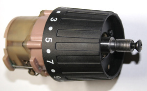
Before starting repair work, you need to get acquainted with the design of this tool and identify elements, which will be required to fix the screwdriver, among them:
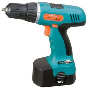
The contact placed on the button will move along the board, taking into account the pressure on the button. The level of the impulse applied to the key depends on the location of the element. The key is a field-effect transistor. The principle of operation will be as follows: the harder you press the button, the higher the value of the pulse on the transistor and the greater the voltage on the motor.
Motor rotation is reversed by reversing the polarity at the terminals. This process takes place using contacts that are switched using the reverse handle.
As a rule, screwdrivers contain collector single-phase DC motors. They are quite reliable and very easy to maintain. Standard screwdriver consists of the following elements:
The gearing system converts the high rotations of the motor shaft into the revolutions of the chuck. Screwdrivers use classic or planetary gearboxes. The first ones are installed very rarely. Planetary gearboxes consist of the following parts:
- sun gear;
- ring gear;
- drove;
- satellites.
The sun gear works by means of the armature shaft, its teeth activate the satellites that rotate the carrier.
A special regulator is installed to regulate the force with which it is supplied to the screw. Typically, there are 15 adjustment positions.
The main signs of breakage spare parts in this case are:
- impossibility of adjusting the number of revolutions;
- impossibility of switching to reverse mode;
- breakdown of the charger;
- the screwdriver does not turn on.
First you need to check the tool battery. If the screwdriver was set to charge, but this did not give results, then you need to prepare a multimeter and try to determine the breakdown with it.
First you need to measure the voltage value of the battery. This value must correspond approximately to the one that is written on the case. If the voltage is low, then you need to identify the faulty part: the charger or the battery. What do you need a multimeter for? We plug this device into the network, then we measure the voltage at the terminals idling. It must be several volts higher than indicated on the design. If there is no voltage, then the charger needs to be repaired.
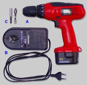
As a rule, all chargers, like most spare parts, are not original, and they are manufactured not in Germany or Switzerland, but in China... But there is nothing wrong with that, the quality usually corresponds to the standard.
BOSH connector is three-pin: one control connector and two power connectors.
Most often, this situation appears - the battery is installed in charging - but the charging process ends in just a few minutes, and the battery is discharged, and the charger stops.
To understand the problem and find the faulty part, you need to disassemble the charger. We unscrew the four screws at the bottom and open the case. In the case, in one compartment there is an AC voltage transformer, and in the other - a rectifier circuit with power connectors and a control chip.
Then we plug in the charger and we measure the current strength on the transformer - if everything is fine, then proceed to the next procedure.
You don't need to touch the control chip and rectifier, they are most likely fine. We pass to the contact group - one control contact and two power contacts. To determine what the malfunction may be, we need to measure the current at the power terminals when the charge is working. Why do we solder to all contacts along a thin wire - so that the voltage can be measured when charging is working.
It is advisable to use several colors of wires in this scheme and, accordingly, to solder them plus and minus. Then we collect the charging and test with a multimeter the current at the terminals when charging.
If the current on the device is unstable and fluctuates in the range from 3-4 to 14-18 volts. Moreover, if you move the battery, then the contact disappears. It is here that the reason lies - during the operation of the device - the terminals are bent and poor contact leads to unstable charging of the screwdriver battery.
That is, it is clear that unstable contact breaks the charging logic - in particular, the third contact, control, it is he who is responsible for what current is supplied to the terminals. It will not be possible to close it, since there is a thermistor inside the circuit of any battery and its resistance changes taking into account the temperature of the spare parts inside the battery. That's right, it protects the battery from overheating and overcharging at the same time. But in this case, there is a way out. We again disassemble the charging, bend the terminals, then use a multimeter to watch the charging process - the current at the terminals will slowly increase and then decrease, and the indicator light on the charging is an additional indicator of operation.
The rate of growth of the current at the terminals indicates another important factor - battery wear. If the current rises very quickly and reaches 18-19 volts, then the battery is in good condition. When the battery is slowly taking charge, there is a high probability that some part of the battery is already unusable and needs to be replaced.
Thus, after the restoration of contact between the charger and the battery, we see normal charging process... If the charging seat is loose, then you need to fix the battery in the desired position with electrical tape. The wires that were soldered for indication, we advise you to leave them with the help of them, it is very easy to determine which spare part is faulty, the battery or charging.
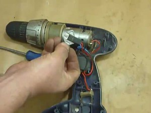
If the charger and the battery are in good order, but the screwdriver still does not work, then you need to disassemble this device.Several wires come out from the battery terminals, you need to take a multimeter and measure the current at the input of the button... If it is present, then you need to get the battery, using the clamps, short-circuit the wires from it. The multimeter should determine the resistance, which should tend to zero. In this case, the spare part is working properly, the problem is with the brushes or other elements. If the resistance is different, then the button will need to be changed. To repair the button, sometimes it is enough to clean the contacts on the terminals with sandpaper. You also need to check the reverse spare part. Repair takes place by cleaning the contacts.
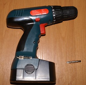
Mechanical breakdowns defined in this way:
- The screwdriver vibrates a lot during operation.
- During operation, the screwdriver emits extraneous noise.
- The screwdriver turns on, but it does not work because of jamming.
- Hits the chuck.
If during operation the screwdriver emits extraneous noise, this means that the bearing or bushings are worn out. To fix this, you need to disassemble the engine, then check the wear level of the bushing and the integrity of the bearing. The anchor must spin freely, there should not be any distortions or friction. These accessories can be purchased at the store and replaced with your own hands.
To the most common malfunctions gearbox designs include the following:
- break in the pin where the satellite is attached;
- abrasion of gears;
- shaft malfunction.
In all cases, it is necessary to replace the defective spare part of the gearbox. All the actions described above must be performed very carefully. Disassembly of the screwdriver must be done in a clear sequence, since some of the spare parts may be lost. Anyone can make an independent repair of a screwdriver, you just need to correctly identify the broken part.
Greetings, dear colleagues. Today we will repair and upgrade the charger at the same time. Bosch AL 1115 CV... Extend his life by improving heat dissipation from vulnerable parts of the device and good ventilation. This charging is widely known for its frequent breakdowns due to overheating and combustion of the power transistor.
I came in a sad state and loaded with a complaint from the owner: “Something cracked there, got cold and stopped working! Didn't do anything special! That I now buy a new one or have a chance to fix it! : - / ". Of course, I calmed him down and praised him for his pragmatism.
I opened the charger with him, saw a burnt board under a burnt resistor, some cracked low-power transistor, a blown fuse. Immediately I was struck by the "radiator" of the power transistor, or rather its absence, because instead of it there was a small iron plate on which the power key was actually fixed. I drew the owner's attention to this deliberate factory jamb (perhaps for the sake of profit) and suggested installing a real radiator instead, as well as drilling more ventilation holes in the device case, since I did not have a small fan and the owner did not want to take out a large radiator outside the case. After agreeing on the price, they hit me on the hands.
After soldering one leg out of the board, it was finally determined to be faulty: the power field-effect transistor V5, an almost cut-off low-resistance resistor R5 (about 2.5 MΩ, at a rate of 3.3 Ohm) in the field source circuit, a punctured low-voltage diode V8 in the binding of the PC817 optocoupler, a burned-out resistor R6 in the circuit of the transistor V6 and the actual transistor of the oscillator V6 itself.
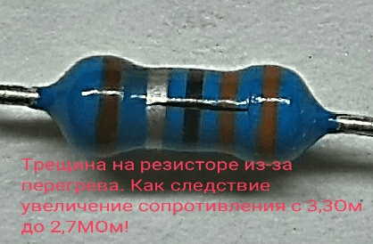
Resistor crack due to overheating
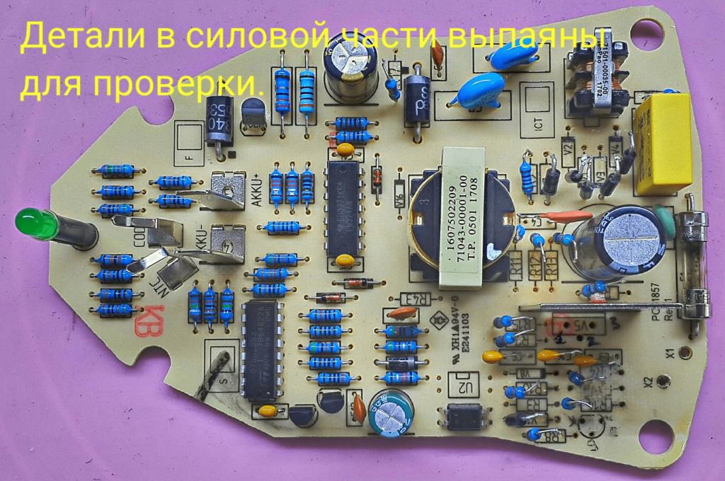
Soldered-out PCB
The problem dug in in the high-voltage power part of the circuit. To make it understandable and easier for you and yourself to repair, "what goes where", etc. decided to draw the faulty part of the circuit from the board.
Using my old technique. Let me explain briefly, it is simple. I draw elements from the side of the board tracks with a gel pen, so as not to get confused and not to return to the beginning every time. After that, I draw a draft on paper, and then the final final version.
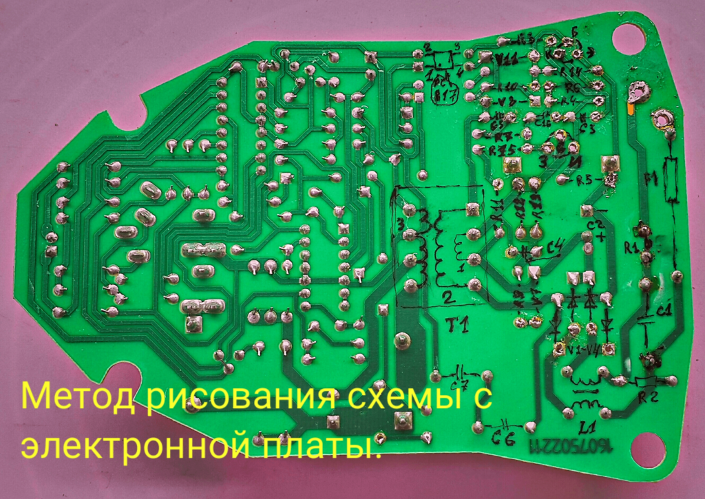
Method for drawing a circuit from the board side
Draft version of the schematic drawing
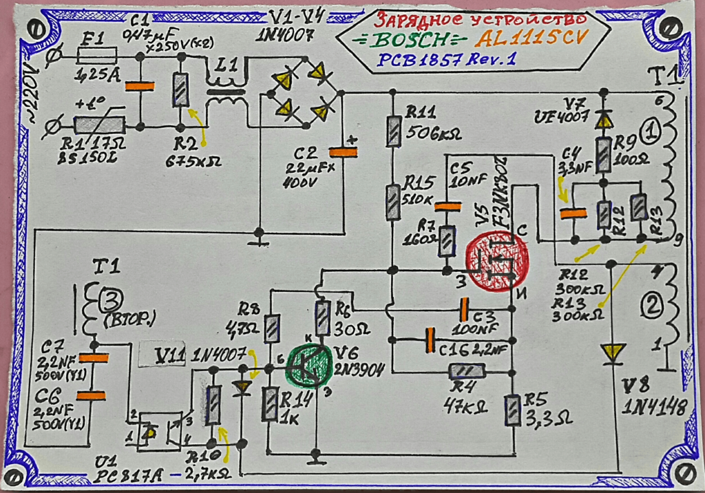
High-voltage part of the circuit Bosch AL 1115 CV
Polevika V5 STP5N80ZF not found, found an analog K3565 (900V, 15A in pulse mode). By and large, any such field worker will do, the main thing is not to be weaker in impulse current and voltage. Low-power transistor V6 2N3904 autogenerator, replaced with a domestic KT3102A, in a metal case and with gilded legs! Anyway, it's expensive to remember and apply cool Soviet transistors in a new way! Diode V8 1N4148 (the Soviet analogue of KD522) was found immediately, as it is widespread. I had to tinker with the resistors R6 and R5, but the Internet helped to understand the native resistance values (the color stripes either turned black or even burned out!) And the number according to the R6 scheme (the place of the board with the number burned out!).
I soldered new parts, washed the board from the helium pen and flux with alcohol, connected it to the network through a 220V × 65W safety light and turned it on. The charger started working, the green LED lit up, with a constant glow. Plugged in the battery - the charging process started, the LED blinked green. After 5 minutes I turned off the charge, my own "radiator" was slightly warm.
I installed a relatively normal radiator, having previously sanded, thoroughly sanded and degreased the surfaces of the radiator and transistor, and lubricated the transistor with thermal grease for normal heat dissipation. For clarity, I drew you a picture of the principle and importance of grinding, see.
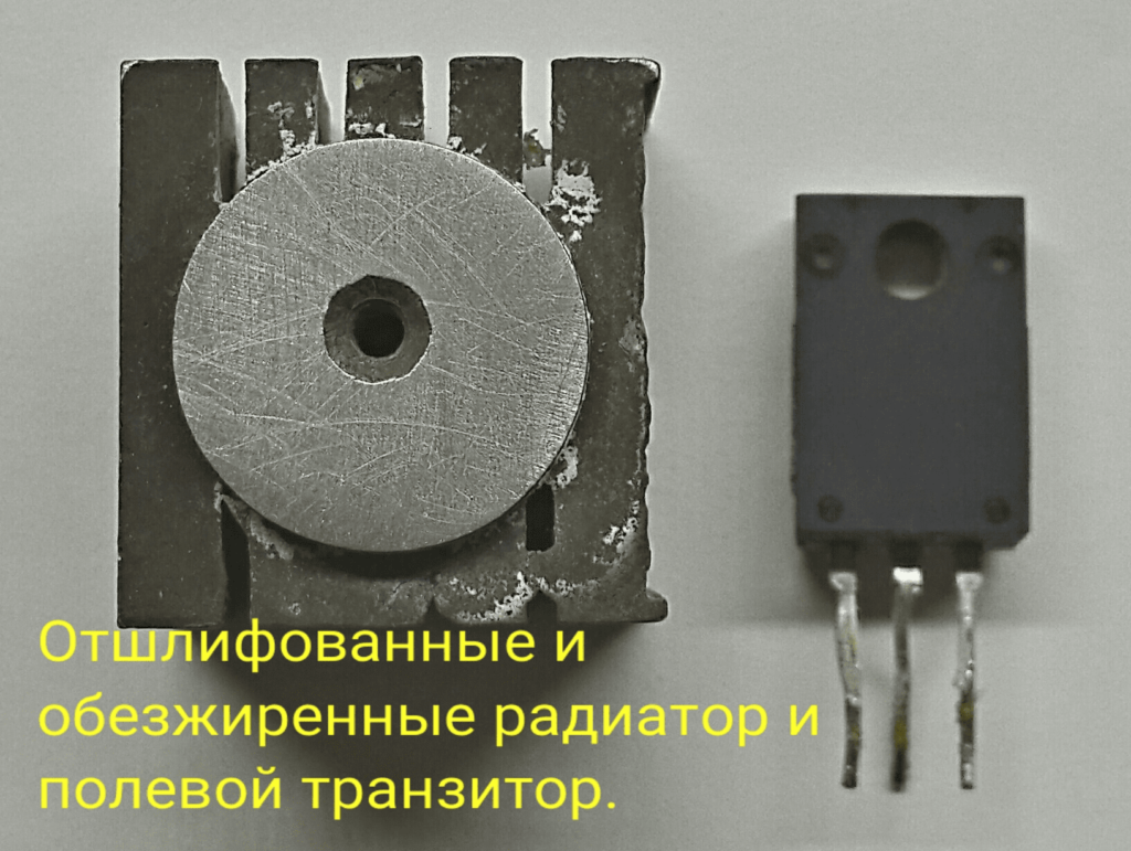
Brushed and degreased heatsink and field-effect transistor
The importance of surface sanding
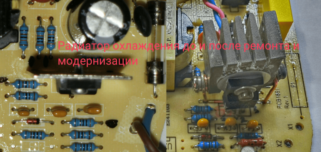
Cooling radiator before and after
A suitable (at a glance, according to approximate calculations) radiator for our field worker did not fit into such a small case, as an alternative to fence the fan to a small radiator or drill more ventilation holes and try not to overheat the device. Or install the radiator outward towards the body. As you know, we stopped with the owner on a cooler-free version, but with new holes.
Since the radiator took up a lot of space, it was necessary to transfer the nearby filtering and power-supplying capacitor C2 to the charger to the side, having previously increased its legs with wiring. Drilled from the heart holes in the bottom and top covers!
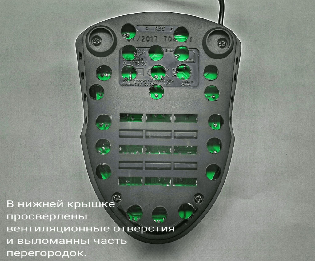
Upgrading the bottom of the charger case
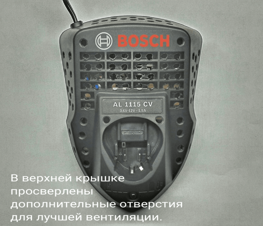
Upgrading the top of the charger case
I collected it, turned it on, after 15 minutes of working with the battery, I measured the temperature under the casing and on the radiator of the field worker. In the case of the board, the temperature turned out to be within the normal range, on the radiator of the field worker is also within the normal range (the approximate critical temperature according to the datasheet of this transistor is 150C °).
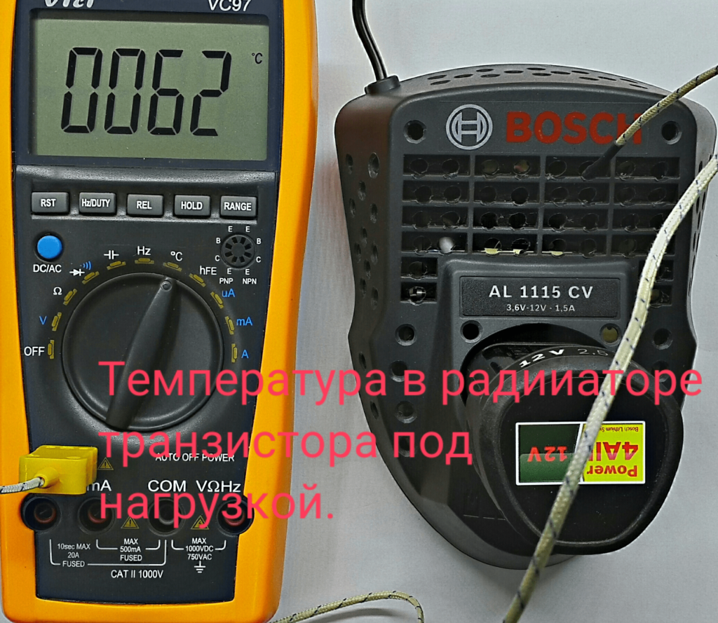
Transistor heatsink temperature
After half an hour, the fully discharged battery was charged, and no overheating was observed.
The result of my struggle to save the drowning charger. As a result, we got a pumped-up charging, creative and stylish modding of the case, the owner's hope for a long work of the device. Satisfaction with the creative work done and a monetary allowance in the amount ... known only to me. 🙂
Good luck with your repairs!
And all the best!
Manual installation of fasteners has always been a laborious and painstaking task. Therefore, space technologies very quickly found their application in terrestrial conditions. The screwdriver has become the most demanded tool in almost every household.But the simplicity of the design and reliability of the instrument does not make the mechanism invulnerable.
During operation, a number of problems arise that can be eliminated on their own or contact the employees of service centers.
The popularity of automation of the process of installation and dismantling of structures gave rise to the mass production of devices with an electric motor. A large number of companies from around the world took up the manufacture of screwdrivers. The palm went to the German power tool manufacturers Bosch.
The screwdrivers of this company are distinguished by solid components, high-quality assembly and a long service life. It is as a result of prolonged and intensive use that this or that problem may appear. This is due to the development of a part or unit of its own motor resource.
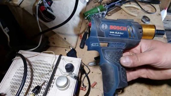

The most common malfunctions of Bosch screwdrivers are:
- battery failure;
- failure of the start button;
- wear of parts of the planetary gear;
- damage to the keyless chuck;
- failure of the electric motor.
- The simplest and most practical way to repair a broken start button for a screwdriver is to completely replace it.
- After purchasing the original spare part, the battery is disassembled. To do this, unscrew the fastening screws around the perimeter of the case and remove its upper part, gaining access to the button.
- Now it is necessary to unsolder it from the motor and remove the connector connecting the switch to the power supply.
- After that, the wires from the electric motor are soldered in place, and the new button is installed in the housing along with the connector.
- Then you need to test the operation of the tool and assemble the body.
One of the main components of a power tool is considered to be a power source. In a screwdriver, this is a battery. It is a battery of galvanic cells connected in series, which are made in the form of cylindrical cans. The size of one element is 33 or 43 mm in height and 23 mm in diameter. The number of cans is determined by the voltage of the assembled tool battery:
- 12 volts corresponds to 10 cells;
- 14 volts will require the installation of 12 elements;
- 18 volts corresponds to 15 elements.
It is not difficult to identify damage to the battery. It is enough to measure its voltage after fully charged. The voltage on one cell is 1.3 volts - the voltage of a fully charged battery of 12 cells should correspond to 15.6-15.7 volts. If the voltage is insufficient, this is a signal for further battery check:
- To do this, unscrew the screws on the case and take out the cassette with the cans.
- Visually inspect galvanic cells for oxidation and degradation.
- Then you need to measure the voltage on each bank. If one or more voltage is absent, then they must be replaced immediately.
- Armed with a soldering iron, it is necessary to remove everything that can prevent you from removing the punched can: the positive wire and the temperature sensor. It is better to insulate the power cable to avoid short circuit.
- Now you need to disconnect the plates welded to the battery, align them for a more reliable contact.
- After that, you need to tin the contacts. To reduce the heating time and temperature, it is advisable to use flux Ф38м. A small amount of it is applied to the contact plate and liquid solder is added. Spreading over the surface, it tinns the contact. This must be done on both sides of the upper and lower contact plates.
- After that, you need to prepare the battery bank itself. Apply flux in the place of its contact with the contact. The plate with the heated solder must be pressed against the jar in the upper end. And the same must be done with the lower contact.
- After that, it is necessary to restore the temperature sensor and the positive contact. Then proceed with the assembly of the repaired battery.
If the battery bank is not broken, but lags behind by 10% according to the voltmeter readings, you can try to reanimate it. As a result of prolonged use under the influence of high loads, some cans dry out. It is necessary to bring them and their action and restore all the processes taking place in the container.
In addition, another option is often used. A hole is drilled in the jar and distilled water is added with a syringe. After that, the element is left for a day. After the specified time has elapsed, the battery is repeatedly discharged and recharged. The hole is covered with silicone.
Another option for returning the operating parameters to the battery is mechanical action on each individual cell. It is easily compressed or deformed. This method does not solve the problem, but the battery is restored for a while.
To restore the performance of rechargeable batteries on the power tool, a charger is used. BOSCH screwdrivers are no exception. One of the failures of the screwdriver is the failure of the charger.
This breakdown manifests itself as follows. The rechargeable battery is set to charge. The device turns on for literally a few minutes, and then turns off, indicating that the charging process is complete. In this case, the battery remains in a discharged state.
To find out the reason for the refusal, you must:
- Disassemble the charger case by unscrewing 4 self-tapping screws. It consists of two sections. In the first, a transformer is installed, in the second - the control board of the device.
- Now you need to apply voltage to the transformer and measure the current strength. If it matches the face value, go to the next operation.
- As a rule, the control chip and rectifier are in good working order in this case, so you need to check the power connectors while the device is operating. A thin wire must be soldered to each contact. They will make it possible to measure the voltage during the operation of the device.
- Charging is turned on and current measurements are taken. If the readings are unstable, up to complete disappearance, then the reason is the bending of the power terminals due to long-term operation of the device.
Restoring contact will allow you to get a full charging process.
Another area requiring close attention is the keyless chuck. It happens that he also fails. Repair consists in replacing it. To remove the quick-release device, you need to unscrew the screw inside the chuck. Please note that the screw is left-handed, so it must be unscrewed by turning it clockwise.
Then the short side of the hex key is inserted into the chuck, clamped and pulled off the thread with a sharp hammer blow. After that, it is unscrewed by hand on the thread. She is normal, right-handed.
After reading the article, we can conclude that the best screwdrivers for use in the household are Bosch tools. They practically do not fail. Their main problem is regular wear and tear due to long-term use or negligence.
| Video (click to play). |

