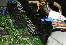
Details: DIY charger repair from a real master for the site my.housecope.com.
The universal charger is a small box that can be placed on a 220V socket and has flexible spring contacts with adjustable size. Under them, you can insert a mobile battery with any current (within reason) and any distance between the contact pads.
At the bottom of the charging case there are four LEDs that show the presence of a 220V network, the battery is connected, the process of charging it - the red LED is blinking, and some other function.
All modes are controlled by a small chip - a charge processor. Naturally, it cannot be replaced. In extreme cases, it can simply be excluded by letting the charging current through a small resistor directly to the battery.
The problem was that if there was a network, the corresponding LED was on, there was no charging process, which could be verified by connecting a milliammeter to the battery break. We open the case and conduct an inspection. As you can see, the switching power supply itself is a complete copy of a standard charger with a 13001 transistor.
Next, the received 9V through the C8550 transistor goes to the battery. the amount of charging current, as well as the duration of the cycle, is determined and controlled by the chip.
Of course, if the problem is in the microcircuit, then all that remains is to supply these 9V directly through a small current-limiting resistor, but fortunately, the semiconductor test revealed the hero of the occasion - it turned out to be a controlled S8550 transistor.
It is unclear what burned it - the output may be closed for a long time, but after replacing it with a new similar transistor, everything worked fine. Testing for several hours showed that all modes were working properly and the battery was disconnected at the end of the cycle.
| Video (click to play). |
The charging current has a value of about 80-100mA and after a certain time (when the voltage on the battery reaches the required voltage), the charge stops and the corresponding LED lights up. I think every radio master should have such a useful device, since there is no need to search for native memory devices even for the most exotic lithium-ion batteries of Chinese mobile phones.
A neighbor asked for a lithium battery charger to be repaired. After the polarity reversal, the charger completely stopped responding to the network and the battery. Since the topic of using 18650 batteries for me has recently been an applied nature, I decided to help my neighbor.
Battery charger for 18650 batteries
According to the neighbor, the algorithm of the device is as follows: when the battery is connected and the mains voltage is supplied, the red LED lights up and stays on until the battery is charged, after which the green LED lights up. Without battery installed and mains voltage supplied, the green LED lights up.
Judging by the label, the charge with a current of 450 mA is carried out in a gentle mode, but as it turned out after opening, this is an economy option)). The charging circuit consists of two nodes: a mains voltage converter based on one MJE 13001 transistor and a charge level controller.
Dismantling the charger from Li-Ion 18650
The converter on one MJE 13001 is often found in cheap chargers for phones, as well as in “frog” chargers. I didn't draw it - I just looked at a similar diagram on the Internet. Plus, minus one resistor / capacitor does not play a big role. The scheme is typical.
The tester rang out the diodes, the zener diode and the transistor, made sure of their integrity.I decided to check the resistors and hit the spot! The resistor R1 turned out to be cut off - 510 kOhm (in the above diagram, this is the resistor R3), which pulls up the supply voltage to the base of the transistor. There was no such thing available, a 560 kOhm resistor was installed instead.
After replacing the resistor, the charging started.
The charger is working - the LED is on
For the sake of interest, I looked into the datasheet of the battery charge controller. It is a microcircuit HT3582DA.
Her clone CT3582 is also common.
As it turned out, two options for switching on the microcircuit are allowed: the 5th pin is closed either with the 8th or 6th pin. In my case, the 5th and 6th were closed. As you can see, the manufacturer claims a maximum of 300 mA. So, on the charging label, great optimism is expressed at 450 mA))). But the most interesting was ahead. Checking the voltage at the charger output with a multimeter showed its reverse polarity.
As it turned out, you first need to insert the battery to determine the polarity by the controller, and then plug it into the network. The datasheet says about automatic detection of battery polarity. In addition, the controller can easily withstand an output short circuit.
To check the results of the repair, I inserted the battery and connected the charger to the network. After a while, I noticed that the red LED does not light up, which means that again something does not work. No crime was detected during the autopsy, all the elements available to the tester to check are in order. I started thinking about the controller, but decided to check the capacitors before starting to search for it in stores. T4 semiconductor tester is available. With its help, electrolytes were tested, and then ceramic capacitors. And then they surprised me a lot. Both 0.1uF capacitors showed the following:
T4 semiconductor tester measures capacitors
For some reason, the 472 pF capacitor turned out to be as much as 8199 pF. Since there was no such thing in the bins, it was necessary to blind the two to a close meaning. I replaced the 0.1 microfarad capacitors with serviceable ones with a preliminary check of the parameters.
After the manipulations, the charger worked properly. The neighbor is happy and spreads information about my magical abilities). The author of the material is Nikolay Kondratyev, G. Donetsk.
Greetings radio amateurs.
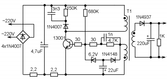
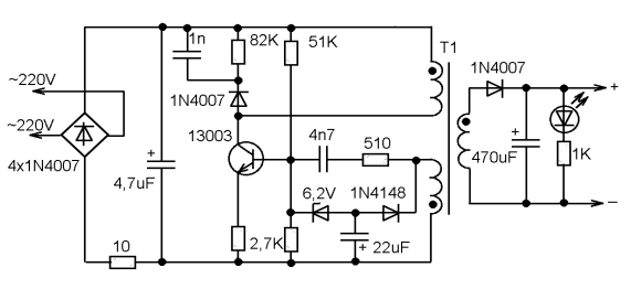
Going through old boards I came across a couple of switching power supplies from mobile phones and wanted to restore them and at the same time tell you about their most frequent breakdowns and elimination of shortcomings. The photo shows two universal schemes of such charges, which are most often found:
In my case, the board was similar to the first circuit, but without an LED at the output, which only plays the role of an indicator of the presence of voltage at the output of the block. First of all, you need to deal with the breakdown, below in the photo I outline the details which most often fail:
And we will check all the necessary details using a conventional DT9208A multimeter.
It has everything you need for this. Continuity mode for diodes and transistor transitions, as well as an ohmmeter and capacitor capacitance meter up to 200μF. This set of functions is more than enough.
When checking radio components, you need to know the base of all parts of transistors and diodes, especially:
Now we are completely ready to check and repair the switching power supply unit. Let's start checking the unit to identify visible damage, in my case there were two burnt resistors with cracks on the case. I did not reveal any more obvious shortcomings; in other power supplies I met swollen capacitors, which also need to be paid attention to in the first place. Some details can be checked without soldering, but if in doubt, it is better to unsolder and check separately from the circuit. Solder carefully so as not to damage the tracks. It is convenient to use a third hand during the soldering process:
After checking and replacing all faulty parts, do the first turn on through a light bulb, I made a special stand for this:
We turn on the charger through the light bulb, if everything works, then we twist it into the case and rejoice at the work done, if we are not looking for other disadvantages, also after soldering, do not forget to wash off the flux, for example, with alcohol. If all else fails and nerves are in the balance, discard the board or solder and select live parts in stock. Everyone is in a good mood. I also suggest watching the video.
JLCPCB is the largest PCB prototype factory in China. For more than 200,000 customers worldwide, we place over 8,000 online orders for prototypes and small batches of printed circuit boards every day!
Failure of a charger for charging starter batteries is unpleasant news for any car enthusiast. Today's article is devoted to the repair of the VZVU OTRE-6,3P-12/6 rectifier charging-recovery device.
The device described below is of very good quality for its time. Made in 1988, it worked without any problems until recently.
Modes of charging the battery, its training (alternately charge-discharge) and active load - in other words, a conventional power supply unit for connecting a carrier, an electro-vulcanizer, etc. - and are now in great demand by any car enthusiast.
After checking the fuse, we begin the repair by studying the circuit.
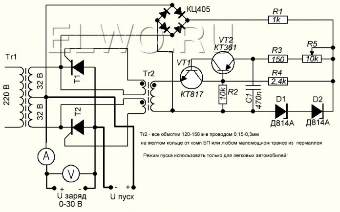
The middle part, which includes five transistors, is a time relay and transistor switches for thyristor control, which operate the device in the “Relay” mode. This node is made on a separate board.
The second board contains a unit for adjusting the charging current (lower part) and controlling the thyristors, which determine the magnitude of this current. On the same board there are thyristors, which ensure the operation of the device in the "Relay" mode, and an automatic protection unit on transistors VT1 and VT2 ..
When inspecting the car charger for external damage, a broken wire was found, we solder it in place.
We turn on the device, the “Network” lamp is on, but there is no voltage at the terminals in all modes, there is no charge.
Having checked the diodes VD1 and VD2 (D242), we turn to the thyristors VS1 and VS2 (KU202G).
As you can see in the photo, the thyristor passes current in one direction.
Broken thyristors can also be detected using a tester, but to detect broken thyristors, you will have to assemble at least the simplest probe to test thyristors.
One of the thyristors of the automation also turned out to be faulty.
After checking all semiconductor devices, we check the electrolytic capacitors for capacity loss and increased leakage current.
Strange, but in this particular case, in 26 years of work, none of them failed.
We assemble the charger and turn it on - the device works only in the “Active load” mode. We continue to study the scheme.
Since the charge current is adjustable, the adjustment unit is beyond suspicion.
When the S1 toggle switch is on (“Charge - Active load” in the “Active load” position), the collector and emitter terminals of the VT1 transistor are closed, thereby disabling the automatic protection unit on the VT1 and VT2 transistors. Since the collector-emitter junction does not open when the toggle switch is off, the elements VT1, VT2 and C2 should be checked first.
After repeated checks of the parts VT1, VT2, VS3, VS4 and C2, a malfunction of VT2 was revealed - when dialing, it behaved as if it were in good condition, but the emitter junction was cut off under voltage.
Now, when turned on, the device started working in all modes.
It remains only with resistor R13 to adjust the discharge time in the “Relay” mode within 10-15 seconds.
Instead of a constant resistor R18 in earlier copies, a trimmer was installed, if it is present, you can correct the charge time with it within 1.5-2 minutes.
After assembly, we check the charger again.
As stated, the discharge time is 15 seconds.
... and the charge time is one and a half minutes.
The result of the repair is three faulty thyristors, one KT361 transistor and a working charger that will last for more than one year.
Increasingly, people have problems with the failure of the charger, which leads to unpleasant consequences, since it becomes impossible to charge the phone if there is no other alternative to the charger. In today's article, we will look at all types of charger breakdowns and repairs.
And so, to begin with, we will determine the main reasons for the failure of the charger, it can be:
- Breakage of the supply wire of the device;
- Damage to the charger block;
- Breakage of contacts, connections or wires in a plug or power supply;
The most common cause of charger failure is a break in internal wires or damaged connections between a plug or block. In such cases, the device can be taken to a service center or repaired by yourself. In this article we will consider the second option, as an example we will use a slim-line charger from Nokia.
- An ordinary multimeter;
- Knife for cutting wires;
- Soldering iron and solders;
- Electrical tape and heat shrink tubing, if available;
- A coil of fine copper wire to connect contacts or damaged parts;
The first thing we will start is looking for damage in the wire or contact connections. It is quite easy to determine the place where the wire breaks down; this is facilitated by a non-standard color or a smaller diameter of the wire itself.
If you could not visually determine the location of the break, then the damage may not be a wire break at all, but a defect in the connections between the device unit or the charging plug.
We start to repair the charger... First of all, we cut off the wire in the region of 7-10 cm from the plug, if the gap is not found, we can reconnect the plug to the power supply. Therefore, it is not advisable to cut the wire close to the plug or power supply unit, since then we will not be able to solder it back.
Next, we clean the wire from insulation (the one on the side of the power supply). We take a multimeter and set the maximum allowable voltage to 20V. (You can learn more about how to use a multimeter in this article). We connect the contacts of the multimeter to the broken and cleaned wires and insert the charger into the network.
If the multimeter shows any value, then there is no damage to the power supply and the wire. In our case, the multimeter showed 7V - this means that the power supply is working properly, since the nominal output voltage of the device is equal to the same value.
We do the same with the charger plug. We clean the wire from insulation and insert a thin wire into the inside of the contact wire, this will be needed to accurately measure the nominal value of the plug with a multimeter.
In the multimeter, select the dialing mode and touch one end of the probe to one of the protected wires, and the other first to the plug, then to the inserted wire. If the multimeter beeps, this will mean that there is voltage between the plug and the wire and that the plug itself is working properly.
If the device does not emit a sound alert, then it follows that the plug is faulty and there may be damage in its contacts. In such cases, you can go to the store and buy a new charger or replace only the plug, but you can also repair it, which we will now do.
If you have another working plug, you can replace it by simply soldering a new one to the old power supply, while it is important to observe the polarity, for this there is a color marking on each cord, all wires must be soldered in the appropriate colors.
But sometimes it happens that there is no color marking, in such cases you need to connect the charger to the network, and the new plug to the phone. Next, you need to connect all the wires of the plug to the wires of the charging block. If the phone goes into charging mode, then you did everything right. If not, change the wire connections until the phone goes into charging mode.
After that, we proceed to soldering. If you have a heat shrink tube, then before soldering, we put it on to one of the wires, then we solder both ends, observing the polarity, then we wrap the junction with electrical tape and put on the heat shrink tube again.
But if you do not have an additional plug, then here you will have to repair the old one. To do this, you need to carefully remove the rubber cover from the old plug with a knife, while trying not to damage the connections of the plug itself.
Then we solder the wires from the charger to the cleaned plug.
After that, we check the functionality of the plug. We turn on the charging unit in the network and connect the cord to the phone. If everything works, we insulate all connections and attach a heat shrink tube to the plug. Then the charger is ready for use.
But it so happens that when you cut the wire and check the voltage, it turned out that it is absent, then in this case you will also have to cut the wire opposite the charging block, retreating about 7-10 cm. It is required to protect the wire leaving the power supply from damage, after which it is necessary to measure the presence of the output voltage. If there is voltage, then this indicates the health of the charging unit.
Next, we check the charger plug in the above way. If the continuity of the plug did not reveal voltage, then it follows that the plug is damaged.
In our case, it turned out that one conductor of the plug was cut off. It is difficult to detect visually. The best option would be to buy a new wire and solder it instead of the old one.
In this case, you also need to observe the polarity, and also check the wire contacts before soldering by plugging the charging unit into the network, and the plug to the phone. If the phone starts to accumulate charge, then you can start soldering the wires, and then insulate them.
If the wire and plug of the charger are working properly, then the damage is most likely in the charger. Perhaps the problem may be the broken contacts inside the charger. To fix the damage, you need to disassemble the charger unit and check all the wires and contacts for a break. If everything is in order with them, then the problem lies in the charger unit itself. At the same time, if you do not possess electrical engineering skills, you will not be able to repair the charging unit. In this case, you will have to buy a new charger or take the old one to a service center.
Perhaps the most "sick" part of a cell phone is its charger. A compact DC power supply with an unstable voltage of 5-6V often fails for various reasons, from the actual malfunction to mechanical failure as a result of careless handling.
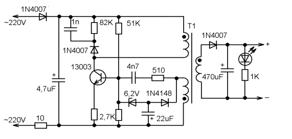
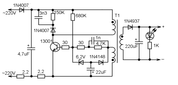
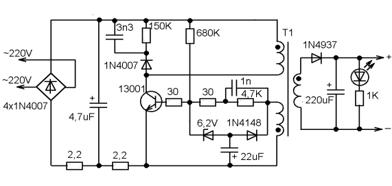
So, what are the "typical" malfunctions? First of all, you should pay attention to the capacitors. A breakdown of the capacitor connected after the mains rectifier is very likely, and leads both to damage to the rectifier and to the burnout of a low-resistance constant resistor connected between the rectifier and the negative plate of this capacitor. This resistor, by the way, works almost like a fuse.
Often the transistor itself fails. Usually there is a high voltage power transistor marked "13001" or "13003". As practice shows, in the absence of such a replacement, you can use the domestic KT940A, which was widely used in the output stages of video amplifiers of old domestic TVs.
Breakdown of the 22 μF capacitor leads to the lack of generation start. And damage to the 6.2V zener diode leads to an unpredictable output voltage and even failure of the transistor due to overvoltage at the base.
Damage to the capacitor at the output of the secondary rectifier is the least common.
The design of the charger body is non-separable. You need to saw, break: and then somehow glue it all together, wrap it up with electrical tape. The question arises as to the expediency of the repair. After all, to charge a cell phone battery, almost any constant current source with a voltage of 5-6V, with a maximum current of at least 300mA, is enough. Take such a power supply and connect it to the cable from the faulty charger through a 10-20 ohm resistor. And that's all. The main thing is not to mix up the polarity. If the connector is USB or a universal 4-pin, connect a resistance of about 10-100 kilohms between the middle contacts (select so that the phone "recognizes" the charger).
Repair of the LI-10C charger from the Olympus camera
About how I managed to repair the charger from the camera in the evening. https://my.housecope.com/wp-content/uploads/ext/1284/
I have never owned a compact digital camera, but here my daughter handed me one of her old Olympus Camedia C-60 Zoom cameras. This camera lay idle for a long time due to the failure of the LI-10C charger.
The battery voltage was about 3.1 Volts, which is less than the threshold after which some chargers recognize the battery and begin to charge it. Anyway, this was the case with my Blackberry battery, which was discharged too deeply.
The LI-12B battery was brought back to life by charging it with a small current, about 100 mA. For this, a simple diagram was assembled. When the battery voltage reached 4.2 Volts, I stopped the charge and checked the camera is working. The camera started working and I began to think about how to repair the charger. https://my.housecope.com/wp-content/uploads/ext/1284/
This is how it looked like the charger I got.
To disassemble the LI-10C charger, it was necessary to unscrew two self-tapping screws, one of which was under the sticker.
Checking the operation of the charger revealed the presence of short-circuited turns in the isolation transformer of the pulse power supply.
The pulse transformer turned out to be non-repairable, and besides, I did not have a suitable ferrite core to wind the new transformer.
The picture shows the printed circuit board of the charger. The arrow marks the transformer DS-4207 KT04044.
I decided I was about to go to our radio market after the weekend, but then I remembered that I have a five-volt charging board for a mobile phone.
I bought this charger once in a faulty state for the sake of a plug case, so that it could fit a power supply for a radiotelephone, which was once designed for a mains voltage of 120 volts.
To check the transformer, I had to first draw a diagram, and then replace all burnt parts.
To my delight, the transformer turned out to be good, and in terms of dimensions it seemed to be just right.
Actually, all further repairs consisted of replacing the transformer.
If you look at the typical switching circuit of the PWM driver microcircuit of this FSDH0165 charger, you will notice that the transformer from the circuit above is functionally not much different from the burned out one.
True, in real charging of the LI-10C, an additional secondary winding IV is used to power the microcircuits, which I had to wind. I wound 14 turns of MGTF wire.
To connect to the printed circuit board, the transformer leads were extended using a rigid insulated single-core assembly wire.
Car battery chargers (ROMs) are abundant in the consumer market. However, any of them may eventually break down during operation. Therefore, car owners need to know how to carry out simple repairs to car battery chargers. Of course, a lot depends on the degree of damage: if it is the simplest one, there are elements that you can repair yourself.
All chargers, based on the principle of operation, are divided into two types: impulse and transformer e. The impulse device works due to the presence of a impulse current converter in it. And inside the transformer charging there is a simple transformer with a rectifier, due to which the ROM weighs more and looks more cumbersome than the pulse one. Pulse-type devices are considered more reliable in operation, but transformer ones are easier to maintain and repair.
If you decide to charge the car battery at home, but are in doubt about your charger, this article is for you. A simple check determines the quality and health of its work.
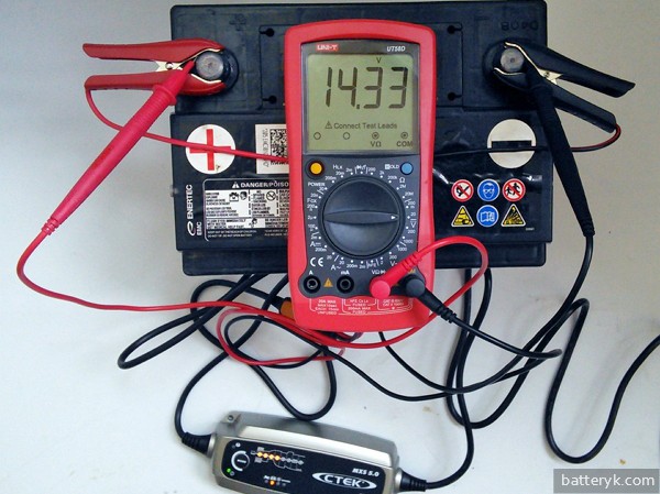
One way is to connect it to the battery and measure the voltage readings with a multimeter. The optimal U in this case is 14 V, it is allowed a little higher, up to 14.4 V. If U is less than 13 V, or the multimeter detects its jumps, then there is definitely a malfunction, and it is necessary to carry out one or another repair of the starting-charger.
If you do not have a battery at hand, you can check the performance of the charger with a simple electric lamp designed for U 12 V. If, when connected to it, the light starts to light up, charging is working normally, and if the light does not light up, the device should be repaired.
The main causes of battery ROM breakdown in cars can be as follows:
- the battery was charged incorrectly ;
- "The contacts are loose" or the wires themselves are damaged ;
- the diode bridge, fuse, ammeter, or another component of the ROM could fail ;
- possible loss of current at a certain stage of its transfer .
You can try to carry out a simple repair of the car charger and, using the example of a transformer-type power supply, consider how this should be done.
Before carrying out any actions with the ROM, be sure to disconnect it from the network. Carefully remove the cover with a screwdriver and first check the integrity of the wiring. It is possible that the matter is in the weakening of contacts, and then the problems can be solved independently using a simple soldering iron.
It happens that some of the plastic connections between the component parts of the charger break or melt. In this case, you can also replace them yourself using a soldering iron and suitable tools at hand.
If all wires and connections are in place, all other elements of the ROM should be checked in turn ... First of all, a multimeter checks the voltage level at the beginning of the electrical circuit, at the input. U is measured across the wire up to where the wire connects to the transformer itself.
If U jumps or does not exist at all, then it is checked:
- fuse (U must be on both sides, on one terminal and on the other, and if there are problems, the fuse is replaced);
- wiring and plug (U is checked according to the same principle, if there are problems, one or the other is replaced);
- checking the transformer itself (measurements of U, if any - the transformer is in good order, if not, you need to check the wafer switch);
- if the switch is faulty, the output U will be absent, but present at the input .
If there is a desire and ability to diagnose a diode bridge, it must be borne in mind that diode bridges can be both monolithic and with the possibility of replacing one faulty diode with another. Monolithic bridges in the event of a malfunction are removed and replaced entirely. As for the voltage supply to the bridge to check its normal operation, U is supplied to the ROM. If the bridge is working properly, no current will be lost either at the input or at the output. If the current does not flow at one of these stages, then you need to separately check each diode, identify the faulty one and replace it.
For a more accurate diagnosis of a breakdown, if nothing was revealed during previous checks, you should check the ammeter. If, when checking the voltage in the ammeter, it is absent, and when its terminals are connected to each other, U appears, then the ammeter is broken, and it is time to repair it.
Thus, it is possible to carry out fault diagnosis and simple repair of chargers for car lead-acid batteries on our own. But when the battery does not charge due to a malfunction of the device, and the motorist does not have the necessary skills in the field of electronics, or it was not possible to fix the ROM himself, it would be best to contact the specialists. As a last resort, you can try to charge the battery without a charger.
Well, it will also be interesting for DIYers of all trades to learn how to make a do-it-yourself battery plug for a battery.
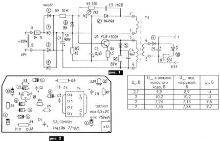
The article describes a typical malfunction of mobile phone chargers. A diagram of one of such blocks is given, drawn up according to a "live" sample, recommendations are given on changing the output parameters and using the repaired block in amateur radio practice.
The fault was the zener diode, conventionally designated in the diagram in Fig. 1 by number 7. It had a leak and "floating" parameters.
The free space in the case of the power supply made it possible to use a chain of several series-connected domestic zener diodes instead. At the same time, it was easy to obtain other, in addition to the passport, output voltage values (see table).
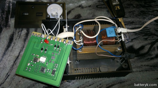
This will probably be of interest to radio amateurs, since they will always find use for such a powerful and small-sized power supply. The layout of the elements on the board is shown in Fig. 2.
The correct operation of some types of car batteries requires periodic maintenance: recharging and adding electrolyte. Of course, now in stores you can choose batteries that do not need supervision at all, but the cost of such devices is quite high. Therefore, experienced drivers, for whom the car is a common technique, purchase standard rechargeable batteries and regularly recharge them with a special device.
However, like any other electrical equipment, this device can break down and then the car battery charger needs to be repaired. This can be done both independently and by handing over the "charger" to professionals.
Now there are several types of devices on the market, which differ not only in name and price, but also in the principle of operation. The division takes place in two planes: a design feature and a work feature.
In the first case, there are:
- Transformer. Here, the design is based on a transformer that lowers the voltage to the desired level so that the battery can be charged.Such devices are quite reliable and charge the car battery well. However, they are rather cumbersome.
- Pulse. Here, the work is provided by a pulse converter, which is considered less reliable. But the obvious advantage of such devices is their low weight and dimensions.
With regard to the principles of operation of chargers for vehicle batteries, the division goes into two categories:
- Charging and pre-starting devices. Easily recognized by the thin wires that must connect the terminals of the charging equipment and the terminals of the battery itself. Effectively recharges or fully charges the battery and can be used even if the vehicle's battery is still connected to the vehicle. Convenience is pretty obvious.
- Starting and charging devices. They are recognized by the presence of thicker wires connecting the battery and the charger. They can work in two different modes, which are switched by a special toggle switch. In one mode, the "charger" delivers the maximum current. In another, it is used for automated charging. Such devices can only be used with a battery that is disconnected from the car. If you forget about it, you can burn many different fuses of the onboard system, or even a few important parts.
It must be understood that this is an electrical device that is assembled according to a certain scheme in order to perform its function. And the more powerful and high-quality the device, the more functions it has, the more complex the scheme of work. Therefore, without knowledge of electronics, without understanding the theory of work, it is not worth disassembling and repairing the battery charger.
However, sometimes a small self-repair is still possible. Especially if a relatively simple transformer-type device has failed. Let's see how it looks from the inside. To do this, just take a screwdriver, unscrew the bolts and remove the top cover. Under it you can see:
- Power transformer. Allows you to give the output different values and voltage range.
- Galent switch. Allows the user to adjust the voltage.
- Ammeter. Monitors the current.
- Diode bridge. These are four diodes combined together. Responsible for rectifying current from AC to DC.
- Fuse. Certain protection against power surges.
What can you check with little understanding of electronics?
Secondly, for devices that are used quite often and intensively, often the wires simply leave the connection points. It is necessary to carefully examine the insides of the device, and check that the fastening of the wiring is sufficiently reliable. If a torn wire is found during visual inspection, then it must be soldered in place. Thirdly, sometimes in cheap "chargers" plastic is used where it does not fit well. For example, once it was necessary to repair a charger for a car battery, inside which a diode bridge was screwed to a plastic stand. Naturally, the plastic eventually melted and the diode bridge moved away from the heat sink plate.
This is where the possibilities of self-repair for a simple layman, as a rule, end.
If the knowledge in electronics is deeper and there is an understanding of how to use testing devices, then you can go further.
- We check the incoming voltage. We go along the power wire and find the place where it is connected to the power transformer. In this place we measure the voltage, thereby excluding malfunctions of the power cable and fuse.
- Checking the output voltage. Now we act from the other side - we look at where the wires going towards the battery are connected. Switch the multimeter to DC current mode and check the voltage. Most likely, there will already be problems here.
- We check the performance of the diodes and the galent switch. To do this, it is necessary to measure the voltage at the input of the diode bridge.Depending on the result of measurements in this place, the conclusion will be obtained - the switch is faulty, or the diodes are faulty. In the second case, you will have to unscrew the entire bridge and check each diode separately. As soon as it becomes clear which one is not working properly, it will be necessary to replace it with a whole one.
In general, a diagram of its operation is attached to each battery charger. People who can read the diagram and understand the general principles of the system functioning, in some cases will be able to independently repair the "charger" of the battery.
If there is no certain knowledge in electronics, then it is not worth doing such work. This is not only a risk to the performance of the charging devices, but also a health risk. It is much easier to contact a professional electrician, who will certainly deal with the problem faster and better.

