In detail: do-it-yourself phone repair from a real master for the site my.housecope.com.
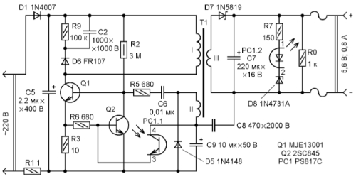
The article describes a typical malfunction of mobile phone chargers. A diagram of one of such blocks is given, drawn up according to a "live" sample, recommendations are given on changing the output parameters and using the repaired block in amateur radio practice.
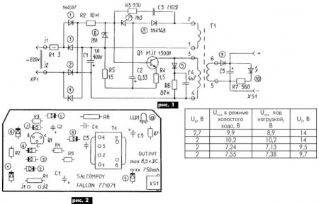
The fault was the zener diode, conventionally designated in the diagram in Fig. 1 by number 7. It had a leak and "floating" parameters.
The free space in the case of the power supply made it possible to use a chain of several series-connected domestic zener diodes instead. At the same time, it was easy to obtain other, in addition to the passport, output voltage values (see table).
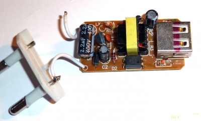
This will probably be of interest to radio amateurs, since they will always find use for such a powerful and small-sized power supply. The layout of the elements on the board is shown in Fig. 2.
 DIY LED flashlight and charger for it.
It has long been known that LED flashlights are very economical, compact and have a longer lifespan. You can easily make an LED flashlight with your own hands or remake an existing one. This requires high-power bright LEDs.
LEDs consume less current, are more durable and more reliable than a light bulb. In addition, they are not afraid of impacts and shaking.
 Diy welding machine from television transformers
Old tube TVs have not been used for a long time. The powerful power transformers used in them can be useful for the manufacture of power supplies, chargers, starters, or by connecting several transformers, you can even assemble a small welding machine!
| Video (click to play). |
They brought me to make a completely new factory-made car battery charger. It did not work for a long time ... More ...
The most common reason for the failure of a charger is a careless attitude towards it during operation.
Phone charger repair
Possible causes of breakdowns of the mobile phone charging unit
1. Broken wire at the plug and at the base of the charging unit. You can break the wires when the charger is on during calls.
You need to pull the plug out of the phone jack not by the wire, but by the plug body.
2. Failure of the elements of the electronic board of the charger. Very often, the charger is left plugged in and is not removed from the outlet. In this case, the entire electronic board of the charger is constantly energized, which reduces the service life of the radio elements of the board.
The wrong order of switching on and off the charger also leads to premature wear of the elements of the block.
If the phone is disconnected from the charger while energized, sudden voltage surges occur that exceed the maximum permissible operating voltage of the cells. This is due to transient processes that occur in the memory when the load is removed (disconnecting the phone) under voltage. With proper operation of the charger, the phone is connected and disconnected with the charger turned off.
You don't need to be a great specialist to find and fix a broken wire from the charging unit to the plug. Wire breakage can be detected when the phone is connected. Having connected the phone to the charger, bend the wire at the plug u of the base of the unit, while simultaneously observing the continuity of the battery charging process.
In these places, wire breaks most often occur. If a break is found at the very base of the plug, then the wire is cut off at a distance of 5-7 mm from the plug.This is necessary in order to be able to solder the whole part of the wire. The soldered wires are insulated separately with a thin heat-shrinkable tube.
When the soldering points of the wires are insulated, a thicker heat shrink tube is put on the plug to stiffen the soldering point. Sometimes a wire break occurs at the very base of the plug, then the plug is completely freed from the plastic seal, and the wires are soldered directly to the plug.
Do not reverse the polarity of the plug wires. The break point is also found with a multimeter in the audible dial mode or visually. The found place of wire breakage is cut with a small margin on both sides. Peel the top insulation off the wire. Then it is cut off, stripped of insulation, twisted and soldered, after putting on a thin heat-shrinkable tube on each wire, and a thicker tube on the common wire.
After soldering, they put thin tubes on the wires and upset them, heating them with a soldering iron. At the end, a thicker tube is put on in place of the upset thin tubes so that the thick tube overlaps them in length. When soldering wires, observe the polarity according to their color. You can purchase a new cord with a plug for your brand of phone from specialized stores. Then phone repair comes down to a simple replacement of the faulty wire.
The type of faulty capacitors
Another common malfunction of a phone charger is a loose contact between the pins of the power plug. The spring-loaded pins of the mains plug often extend from the contact pads on the PCB. To eliminate such a malfunction, it is enough to bend these contacts inside the block.
Open the cover of the block. It is good if there are screws securing the charger cover, and if they are soldered. In this case, you need to cut a slot around the entire perimeter of the cover with a fine-toothed metal hacksaw blade. Having eliminated the malfunction, the lid is closed and fixed with tape 1 cm wide.
More complex, but quite affordable for an electrician are device breakdowns associated with the repair of elements of the phone charger board. First of all, they open the memory and take out the board. Repair begins with a visual inspection of the elements of the printed circuit board and the condition of its tracks.
Pulse charger circuit for phone
When inspecting the elements, pay attention to the swelling of the upper part of the capacitors, darkening and violation of the integrity of the resistors. Darkening of the resistors and the tracks below it indicates that the operating temperature has been exceeded. In this case, the resistor itself is checked for resistance and the diodes and transistors are ringed.
The pinout of the transistors and the memory circuit for your phone brand can be found on the Internet. If it was not possible to visually detect a malfunction, turn on the device and measure the input mains voltage. If the mains voltage is present and a faint sound of the pulse transformer is heard, then the output voltage of the unit is measured.
It should be within 7.5V no load. If there is no output voltage, and the transformer is buzzing, then you need to watch the resistance of the output winding of the transformer and the elements that follow it. Since the charger of mobile phones is assembled according to a pulse circuit, when repairing them, you can focus on the article "Repairing a switching power supply with your own hands."
Greetings radio amateurs.
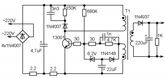
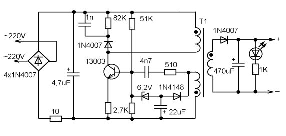
Going through old boards I came across a couple of switching power supplies from mobile phones and wanted to restore them and at the same time tell you about their most frequent breakdowns and elimination of shortcomings. The photo shows two universal schemes of such charges, which are most often found:
In my case, the board was similar to the first circuit, but without an LED at the output, which only plays the role of an indicator of the presence of voltage at the output of the block.First of all, you need to deal with the breakdown, below in the photo I outline the details which most often fail:
And we will check all the necessary details using a conventional DT9208A multimeter.
It has everything you need for this. Continuity mode for diodes and transistor transitions, as well as an ohmmeter and capacitor capacitance meter up to 200μF. This set of functions is more than enough.
When checking radio components, you need to know the base of all parts of transistors and diodes, especially:
Now we are completely ready to check and repair the switching power supply unit. Let's start checking the unit to identify visible damage, in my case there were two burnt resistors with cracks on the case. I did not reveal any more obvious shortcomings; in other power supplies I met swollen capacitors, which also need to be paid attention to in the first place. Some details can be checked without soldering, but if in doubt, it is better to unsolder and check separately from the circuit. Solder carefully so as not to damage the tracks. It is convenient to use a third hand during the soldering process:
After checking and replacing all faulty parts, do the first turn on through a light bulb, I made a special stand for this:
We turn on the charger through the light bulb, if everything works, then we twist it into the case and rejoice at the work done, if we are not looking for other disadvantages, also after soldering, do not forget to wash off the flux, for example, with alcohol. If all else fails and nerves are in the balance, discard the board or solder and select live parts in stock. Everyone is in a good mood. I also suggest watching the video.
Perhaps the most "sick" part of a cell phone is its charger. A compact DC power supply with an unstable voltage of 5-6V often fails for various reasons, from the actual malfunction to mechanical failure as a result of careless handling.
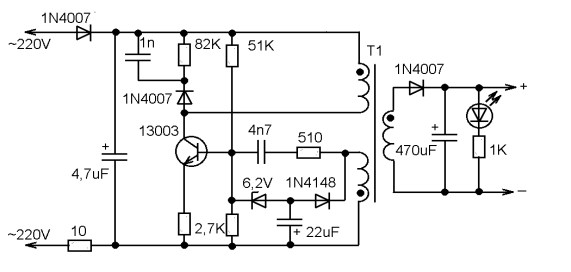
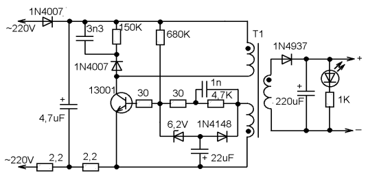
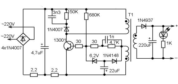
So, what are the "typical" malfunctions? First of all, you should pay attention to the capacitors. A breakdown of the capacitor connected after the mains rectifier is very likely, and leads both to damage to the rectifier and to the burnout of a low-resistance constant resistor connected between the rectifier and the negative plate of this capacitor. This resistor, by the way, works almost like a fuse.
Often the transistor itself fails. Usually there is a high voltage power transistor marked "13001" or "13003". As practice shows, in the absence of such a replacement, you can use the domestic KT940A, which was widely used in the output stages of video amplifiers of old domestic TVs.
Breakdown of the 22 μF capacitor leads to the lack of generation start. And damage to the 6.2V zener diode leads to an unpredictable output voltage and even failure of the transistor due to overvoltage at the base.
Damage to the capacitor downstream of the secondary rectifier is the least common.
The design of the charger body is non-separable. You need to saw, break: and then somehow glue it all together, wrap it up with electrical tape. The question arises as to the expediency of the repair.After all, to charge a cell phone battery, almost any constant current source with a voltage of 5-6V, with a maximum current of at least 300mA, is enough. Take such a power supply and connect it to the cable from the faulty charger through a 10-20 ohm resistor. And that's all. The main thing is not to mix up the polarity. If the connector is USB or a universal 4-pin, connect a resistance of about 10-100 kilohms between the middle contacts (select so that the phone "recognizes" the charger).
Now, as never before, the number of gadgets per person has reached the maximum value.
Phones, tablets, laptops, various wireless headsets - all this abundance of technology has a power source and, accordingly, a charger for it.
Chargers are often carried with them in a bag or pocket, and so that they take up a minimum of space, their cords are twisted with a bend and a stretch.
This, in turn, leads to an almost imperceptible wire break and inoperability of charging. Just break in the cord - this is the most common breakdown in such types of devices, and, frankly, it is a pity to throw it away because of this.
Yes, you can certainly buy a new one and not suffer, but if the device is non-standard, for example, an old model phone, then it is not always possible to find such a charger. And at the "flea market" you can slip a block with the same problem, and no one needs extra spending.
Therefore, repairing a charger is a useful and worthwhile business.
Below, in this article, a simple repair method that does not require special equipment will be described, which will give your charge a second life.
In the photo - charging with a problem in the cord.
The cliff is not always visible to the naked eye. It can be hidden under the thickness of the main (top) insulation and remains practically invisible.
But, as practice shows, the fracture occurs most often near the entrance to the block or at the base of the plug.
To locate the break, just connect the included charger to the phone and wiggle the cord in a suspicious place.
As soon as you see that the charging "went" for a moment, it means that there is a break in the place where you were moving at that moment.
In this case, looking closely, the break and cliff were visible even without stirring. It just turned out at the entrance to the power supply.
The main problem in the repair of such blocks is that it is not collapsible. Therefore, to get to the electronic board, you need to be careful and some effort.
Using a screwdriver and a knife, pry off the base of the rear cover and remove it.
Pry should be at the point where the cord enters the device. If the entry is too tight, you can cut the rubber strap slightly.
This must be done carefully so as not to cut the wire at all.
Having poked it up with a screwdriver, we try to lift the cover up.
It may happen that it cracks in half, but more often, as in this case, the cover was removed entirely, without damage.
It was even seen that it had latches, and in the charger case there were recesses for them.
This means that it is possible, after repair, to put the cover in its place without using glue.
When the cover is removed, you need to pull the printed circuit board out of the case. Since it "sits" tightly, a screwdriver will help to get it out. Leaning the blade of the screwdriver against the body and hooking it with the end of one of the soldering points, we pull the board out.
The structure of the case is such that when the board is inserted inside, its input contacts are connected to the clamps of the pins of the power plug. Therefore, when installing the board back into the case, you need to take this point into account.
The photo below shows the board with all its "insides". The wires are soldered at the bottom.
View from the opposite side.
And here in the photo are the tracks for the input contacts.
The wire will have to be cut below where the damage is. But it is very important to remember which wire is "+" and which is "-".In some cases, the wires are colored accordingly, red is the positive and black is the negative.
With color marking, you can safely cut, and then just solder the wires, observing the polarity.
In our case, the wires are of the same color, but since the cord is flat, you can trace from which side of the cord the wire goes to minus, and from which to plus. Mark and then crop.
Next, unsolder the remaining ends from the board and prepare holes for soldering a new wire.
Without losing the label, strip and tin the wires on the cord.
Solder them one by one to the board, observing the polarity.
The PCB usually has polarity markings at the soldering point.
To prevent the cord from dangling at the outlet, we wind a bandage of black electrical tape around its entrance part. The thickness of the band should be such that it fits into the slot for the wire and locks into it.
Before installing the cover, we check the operation of the device. We plug it into the network and connect it to the phone. If the phone is not with you at the moment, we use a DC voltmeter.
Since the internal contact in the socket has a very thin tube, and the probe of the device does not go into it, you can use a piece of thin copper wire to check.
Having inserted it into the tube of the internal contact, we connect the probes of the measuring device to it and to the external output of the plug.
The voltmeter shows that voltage is present, which means that the breakdown has been repaired.
Now we snap on the back cover.
We connect the phone and rejoice at the results of the work done.
On our website information will be collected on the solution of seemingly hopeless situations that arise for you, or may arise, in your everyday life at home.
All information consists of practical advice and examples on possible solutions to a particular issue at home with your own hands.
We will develop gradually, so new sections or headings will appear as materials are written.
Good luck!
Home radio - dedicated to amateur radio. The most interesting and practical circuits of devices for the home will be collected here. A series of articles on the basics of electronics for beginner radio amateurs is planned.
Electrician - given detailed installation and schematic diagrams concerning electrical engineering. You will understand that there are times when it is not necessary to call an electrician. You can solve most of the questions yourself.
Radio and Electrics for beginners - all information in the section will be completely devoted to novice electricians and radio amateurs.
Satellite - describes the principle of operation and configuration of satellite television and the Internet
Computer - You will learn that it is not such a terrible beast, and that you can always cope with it.
We repair ourselves - illustrative examples are given for the repair of household items: remote control, mouse, iron, chair, etc.
Homemade recipes - this is a "tasty" section, and it is completely devoted to culinary.
miscellanea - a large section covering a wide range of topics. These are hobbies, hobbies, useful advice, etc.
Useful little things - in this section you will find useful tips that can help you in solving everyday problems.
For home gamer - the section is entirely devoted to computer games and everything connected with them.
Works of readers - the section will publish articles, works, recipes, games, advice from readers related to the topic of home life.
Dear visitors!
My first book on electrical capacitors, dedicated to novice radio amateurs.
By purchasing this book, you will answer almost all questions related to capacitors that arise at the first stage of radio amateurism.
Dear visitors!
The site contains my second book on magnetic starters.
By purchasing this book, you no longer have to look for information about magnetic starters.Everything that is required for their maintenance and operation, you will find in this book.
Dear visitors!
The third video for the article How to solve Sudoku has been released. The video shows how to solve a difficult Sudoku.
Dear visitors!
A video was released for the article Device, circuit and connection of an intermediate relay. The video supplements both parts of the article.

 DIY LED flashlight and charger for it.
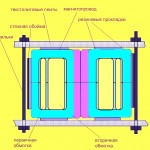 Diy welding machine from television transformers