In detail: resanta 160 DIY repair fuse from a real master for the site my.housecope.com.
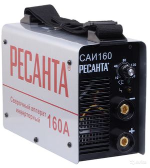
Once the Resant SAI 250PN welding inverter fell into my hands. The device, without a doubt, inspires respect.
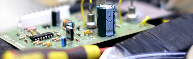
Those who are familiar with the device of welding inverters will appreciate the power of the electronic filling.
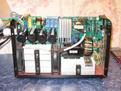
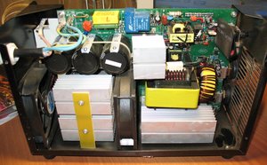
As already mentioned, the filling of the welding inverter is designed for high power. This can be seen from the power section of the device.
The input rectifier has two powerful diode bridges on the radiator, and four electrolytic capacitors in the filter. The output rectifier is also complete with: 6 dual diodes, a massive choke at the output of the rectifier.
three ( ! ) soft start relay. Their contacts are connected in parallel to withstand the large current surge when welding starts.
If we compare this Resanta (Resanta SAI-250PN) and TELWIN Force 165, Resanta will give him a dashing head start.
But, even this monster has an Achilles heel.
The cooling cooler does not work;
There is no indication on the control panel.
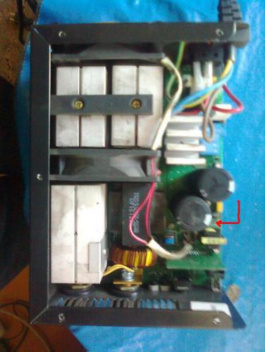
After a cursory inspection, it turned out that the input rectifier (diode bridges) turned out to be in good order, the output was about 310 volts. Therefore, the problem is not in the power section, but in the control circuits.
External examination revealed three burned out SMD resistors. One in the gate circuit of the 47 Ohm field-effect transistor 4N90C (marking - 470), and two at 2.4 ohms (2R4) - connected in parallel - in the source circuit of the same transistor.
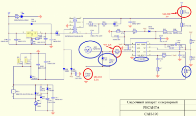
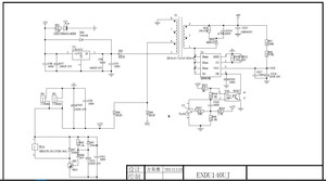
4N90C bipolar transistor (FQP4N90C) is controlled by a microcircuit UC3842BN... This microcircuit is the heart of the switching power supply, which powers the soft-start relay and the integrated stabilizer at + 15V. He, in turn, feeds the entire circuit, which controls the key transistors in the inverter. Here is a piece of the RESant SAI-250PN diagram.
Video (click to play).
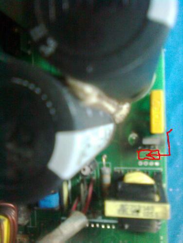
It was also found that there is also a resistor in the power circuit of the UC3842BN (U1) ShI controller in the open circuit. In the diagram, it is designated as R010 (22 ohm, 2W). It has the reference designation R041 on the printed circuit board. I will warn you right away that it is quite difficult to detect a break in this resistor during an external examination. A crack and characteristic burns can be on the side of the resistor that faces the board. This was the case in my case.
Apparently, the cause of the malfunction was the failure of the UC3842BN (U1) ShI controller. This, in turn, led to an increase in the consumed current, and the resistor R010 burned out from a sharp overload. SMD resistors in the FQP4N90C MOSFET circuits played the role of a fuse and, most likely, thanks to them, the transistor remained intact.
As you can see, the whole switching power supply unit on the UC3842BN (U1) has failed. And it feeds all the main units of the welding inverter. Including soft start relay. Therefore, welding did not show any "signs of life."
As a result, we have a bunch of "little things" that need to be replaced in order to revive the unit.
After replacing the indicated elements, the welding inverter turned on, the display showed the value of the set current, the cooling cooler clinked.
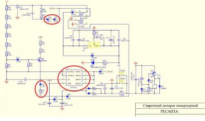
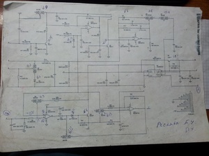
For those who want to independently study the device of the welding inverter - the complete schematic diagram of "Resant SAI-250PN".
0
Oyawrik 04 Apr 2014
Tell me the name of the microcircuit with eight legs, otherwise, while one friend of mine was soldering it, all the information on it was burnt. Resanta 160 sais.
2
mitka51 04 Apr 2014
Show me on the diagram.
2
morgmail 04 Apr 2014
mitka51 , it is pointless.
while one friend of mine was drinking it, all the information on it was burnt.
0
alek956 05 Apr 2014
mitka51, this is pointless.
1
morgmail 05 Apr 2014
alek956 , did not get the point.
0
Oyawrik 05 Apr 2014
Show me on the diagram.
0
Cactus78 05 Apr 2014
1
Alex_Nemo 24 Apr 2014
Elements with “typical” failure are circled in red. Blue when 3842 fails, etc. In your case, change both. Instead of R013 (SMD 1206), it is necessary to carefully solder in its place a 0.5W output resistor with an insulating tube put on it. The transistor changes to any but at 900V
0
Lech the Welder 24 Apr 2014
Not the first person to face this problem.
Sly microcircuit. On sale a rarity, there are no analogues.
0
tehsvar 24 Apr 2014
Why is that? It's pretty common. And not a deficit. The defect is standard on Resant (and her clones).
0
Lech the Welder 25 Apr 2014
And the reason is pretty simple! Before turning off and turning on the device, you need to turn off the current to the end (as the instructions say) and due to a break in the electrical network
Why is that? It's pretty common. And not a deficit. The defect is standard on Resant (and her clones).
In any case, it is almost impossible to find one in the countryside!
1
LamoBOT Apr 25, 2014
No need for welding no matter that.
I have a problem, water is constantly on overload, the output is 2 volts, the diodes are normal at the output, I changed Q2 D3 D4 D7 D8 R5 A3120. On 5 and 8 legs, a3120 has 26 volts on one and 24 volts on the other. on the PWM board on 3 leg 5 volts on 5 leg 15 volts. Overload also burns under load. What else could be the problem?
I need the help of specialists, friends brought SAI160, I opened the device and saw the following picture: Viper22 and R37 exploded, diodes D16, D15 (ER2D) ring shortly, Zener diode DZ8 is also short-circuited. I changed all these parts: U1, Q4, D15, D16, R37, C21-24. U2 (also changed it just in case). When turned on, the vtilators twitch and stand (11.6 v is supplied), the relyushka turns on, a strange sound comes from the board after turning on, as if the pulse generator is closed or very loaded, D20 and D18 begin to warm up strongly, viper22 is also warming up. I did not keep it turned on for more than a minute, it is clear that it does not work correctly. Can you tell me who has met with such a breakdown. There is no oscillograph, I can not see what viper22 produces.
1
tehsvar Jul 21, 2014
When turned on, the vtilators twitch and stand (11.6 v is supplied)
So temporarily open the fans and measure what is the output of the welder? What is the voltage? Check the fans from a separate power supply. They could well have burned out, tk. there is also a schematic inside them.
gonchiy Did the power transistors themselves ring?
So temporarily open the fans and measure what is the output of the welder? What is the voltage? Check the fans from a separate power supply. They could well have burned out, tk. there is also a schematic inside them.
Logically, I'll try. Do you think they load so much that the diodes and U1 are heating up? What voltage should the output be? no experience in repairing welding inverters
0
tehsvar Jul 21, 2014
I don’t remember what tension should be. There, the operating voltage is written on the fans. This is something like it should be. A shorted fan will give a considerable load. Almost short. Therefore, the diodes are heated. They are in a serial winding circuit in front of them.
1
Oyawrik 22 Jul 2014
Hands did not reach my resants. But I found a microcircuit worth 50 rubles, I took it to a specialist. He soldered it. And then I soldered for an hour, which I don't know, in short, I took my welding and gave it to the store where I bought it. I was given a guarantee there for 6 months upon purchase. At the moment, she is a little over a year old, but she was assured that they are being renovated in the Regional Center in Kaliningrad quickly and conscientiously. So everyone should mind their own business. Even the body master can repair televisions, but he does not climb into welding. This is me about my friend. So find the address of the warranty workshop in the book from the device and trust the specialists.
1
tehsvar 22 Jul 2014
So everyone should mind their own business.
It would be nice that everyone would understand this!
0
Cactus78 22 Jul 2014
Even the body master can repair televisions, but he does not climb into welding. This is me about my friend.
If this master knows how to read diagrams and understands what's what, then he should have figured it out. Another question is if the necessary parts are not at hand.
Do-it-yourself restoration and repair of a welding inverter is possible only if you have sufficiently confident knowledge in the field of electrical engineering and electronics. A rather complex diagram of the Resant apparatus (or another of the same type) requires the use of special equipment to diagnose the causes of the malfunction.
The inverter unit has a rather complex electronic circuit. An apparatus of this class is characterized by the presence of power converting circuits on semiconductor elements, electronic control of operating modes. Without understanding the essence of the work of all these elements, self-repair is impossible.
The main reason for the breakdown of the Resant's apparatus is considered to be overheating of individual structural units. At the same time, such an opportunity exists both for reasons of malfunction of the cooling system, and with the wrong choice of welding modes.
All elements of the cooling system are subject to mandatory checks.
To determine breakdowns, in most cases, you will have to check the main elements of the electronic circuit, special attention should be paid to semiconductor devices.
It is clear that the repair of an inverter device is impossible without a soldering iron and consumables for it (solders, fluxes). But the main devices will be required precisely for diagnosing a malfunction.
Voltmeter, ohmmeter, ammeter. It is best if you have a combined device at hand that can determine all the parameters of the electrical circuit.
An oscilloscope is required to check the operating parameters of the control unit
The presence of such a minimum set of equipment will make it possible to identify all the main malfunctions characteristic of Resant's units.
The main malfunctions that can be eliminated on your own include:
No welding current with input voltage present. Most often, the reason for this is the failure of the fuses, but malfunctions in any part of the electrical circuit are quite possible.
Even setting the device to the maximum operating mode in terms of power does not allow obtaining the welding current of the required strength. In most cases, the reason lies in poor contact at the terminals or insufficient voltage in the power supply network. Much less often, a malfunction is caused by breakdowns in the power unit of the device.
The reason for the permanent shutdown of the Resant inverter may be the presence of a short circuit in any parts of the circuit or a malfunction of the elements of the cooling system. Inverter shutdowns indicate the normal operation of the device's overheating protection elements.
The cause of the instability of the welding arc can be a breakdown in the control unit or power circuits of the unit.
Particular attention must be paid to the selection of an acceptable operating mode. With constant overloads, even such a reliable device as the Resanta will last much less than the estimated period. Pay attention to the appearance of any unusual noise or heating of the case or other elements of the device. These signs indicate imminent breakdowns in the near future.
All the main measures for the repair of the device can be divided into the following stages:
An external inspection of the inverter housing, checking the condition of the supply and welding cables should be carried out when any signs of malfunctions appear. In some cases, poor contact on various connections can cause unstable operation of the unit. When inspecting, pay attention to mechanical damage, possible signs of a short circuit that has occurred. Be sure to check the integrity of the fuses and tighten all existing contacts.
The next step is to open the case of the device, and in the same way check the condition of all the main elements. In addition, you should check the parameters of the input and output voltage and current.
If the damage to the electrical circuit could not be identified, then it is necessary to check the condition of the power unit, as well as the control system of the device.