In detail: do-it-yourself subwoofer repair from a real master for the site my.housecope.com.
Many motorists want to save on little things, so they are eager to learn how to repair a subwoofer with their own hands. At the same time, having little professional knowledge in this area, it is quite possible to make home repairs of the subwoofer with your own hands.
However, some repair actions for the Sven car subwoofer unit should be performed exclusively in a car center. By the way, you don't have to carry the subwoofer if the amplifier, suspension or one of the speakers is out of order.
The question of how to repair a subwoofer often arises among the owners of not only automobile, but also the rest of the audio equipment, since no one wants to give up excellent acoustics.
You can carry out high-quality repair of car subwoofers by talking with professionals or by watching the corresponding video on Internet resources. At the same time, repairing a subwoofer is available to everyone who has a little free time, perseverance, and also owns a soldering iron or a tester.
It is worth noting that you can only repair a subwoofer after understanding its device and identifying the problem.
For example, in an ordinary home or car subwoofer, the following may fail:
The reasons for the failure of the amplifier or speakers, as well as its other parts, include:
- violation of heat exchange;
- accumulation of dust or dirt;
- lack of voltage at the output from the power unit;
- swollen capacitors;
- lack of current on the supply element of the unit;
- burnt out coil of the transformer.
| Video (click to play). |
Moreover, all these problems are solved simply and easily, because:
- the reel is rewindable;
- dust and dirt can be really cleaned;
- swollen capacitors are subject to replacement, which should be unsoldered and replaced with those purchased in the store;
- the diffuser is easy to glue with adhesive tape, having previously coated it with rubber-based glue.
If a person does not have the slightest experience in this repair or does not know how to handle a soldering iron, then he simply must turn to professionals, and certainly, one cannot rewind the transformer coil, since it can be irrevocably ruined.
The fact is that repairing a subwoofer amplifier is not difficult, but you will not be able to figure it out without delving into the main features.
When starting to repair a car subwoofer, you should:
- remove the amplifier from the vehicle;
- unscrew the metal plates;
- consider them more closely, since the problem may be in the burned or melted amplifier plates.
How to repair a Sven subwoofer if the amplifier plates are out of order? It is worth going to the car market and purchasing similar or more powerful records and a tube of thermal paste.
After that, the following actions are performed:
- wipe all parts of the subwoofer amplifier with alcohol;
- solder to the desired place on the plate;
- smear everything with thermal paste;
- collect the entire structure back;
- install on the car and check after a while.
In order to make a high-quality repair of the subwoofer speaker, you need to decide what exactly to fail in it. To practice repairing the speaker, you should take old speakers that are out of order, for example, BW PV1, Sven, Infinity.
Then you should disassemble the speaker and follow several consecutive steps, including:
- soften the glue that binds almost all parts of the speakers;
- this can be done with a syringe with a needle and a high-quality solvent;
- separate all parts from each other, not forgetting about the dust-type cap;
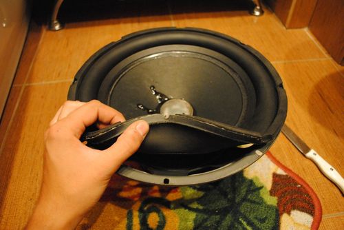
- disconnect the diffuser suspension from the basket of the upper speaker;
- separate the centering washer of the lower suspension by saturating it with solvent;
- wind the coil on a blank, and in two layers, using a thin wire.
By the way, a cylinder made of aluminum can serve as a frame for the coil. In this case, you can rewind this coil with wires of increased cross-section, however, its parameters should be close to the previous one. That is, if a wire with a cross-section of 0.45 millimeters was used for a burned-out coil, then an analog of 0.40 millimeters can be successfully used.
High-quality repair of the Sven subwoofer is carried out only after familiarization with its technical parameters, which are stated in the instructions, in order to determine the possibility of switching the phase, weight, diameter, output power, voltage, frequency range.
At the same time, before repairing a home or car Sven subwoofer with your own hands, you should understand that it will be much more difficult to do this than fixing a breakdown in a BW PV1 or Infinity.
For example, to repair the amplifier of a car subwoofer, you will have to unscrew at least a dozen self-tapping screws in order to get close to the electronics and get a solid block.
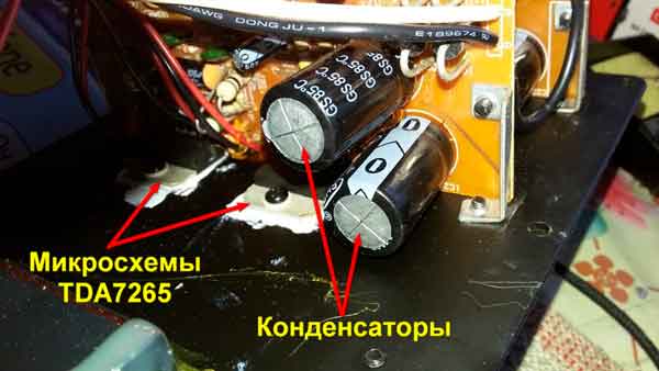
Most often, microcircuits and transistors fail on this model, including a power amplifier of the TDA2030 type, since it does not tolerate short circuits, increased load, overheating or adhesion of dirt.
DIY subwoofer repair - one of the most common breakdowns occurs in the amplifier, which is built into the subwoofer. Many inconveniences are caused by network distortions in the sound, it is the frequency of 50 Hz that brings the most low-frequency interference into the sound path. Therefore, most often you have to deal with this frequency as a hindrance.
Penetrating into the acoustic circuit, this noise creates an unwanted low-frequency hum in the dynamic radiators. One of the effective options for reducing such a defect is to install large capacitors in the supply voltage circuit to smooth out the rectified voltage. As a rule, in circuits assembled on transistors or microcircuits, the culprit is an electrolytic capacitor in the filter circuit that has become unusable. Therefore, noise distortions appear in the speakers.
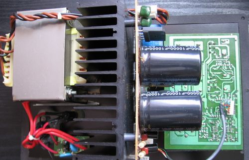
DIY active subwoofer repair and in the process of searching for the cause, we dismantle the heat sink and the following picture appears before us: one of the capacitors has become "pregnant" (it can be seen in the picture). In addition, the contact pad was torn out on the textolite printed circuit board.
For a high-quality amplifier repair, it is necessary to change both capacities at once. Since the second condenser, too, could have lost some of its capacity, and this pair must be identical. Therefore, we change the pair at once, so it will be more reliable and will last longer. In addition, as it turned out, the outer shell of the capacitor burst from internal pressure, and the electrolyte leaked out and stained the board.
We solder the problem capacities, and instead of them we install new capacitors, preferably from well-known companies.
Next, you need to clean the printed circuit board with alcohol from the electrolyte that has got on it, put the containers in place, not forgetting to observe the polarity and solder.
In my case, I had to format the pins of the new capacitors a little, since the holes in the board were slightly wider in the centers. After molding, they fit perfectly into place. But still, for greater reliability, it is better to treat the base of the tanks with thermal glue or epoxy glue to resist vibration inside the subwoofer.
What should be done when the LEDs for visual control over the operation of the device indicate that everything is normal, but one channel still does not work. This problem may also indicate a malfunction in the amplifier. However, you should first check visually and by ringing the signal path going from the sound source to the subwoofer.
In addition to the above described repair of the printed circuit board to replace swollen capacitors, you need to check the output transistors or integrated circuits. It is also very likely that the fault is in the power supply, which does not supply the circuit with the required supply voltage. In fact, any radio equipment should always be repaired by checking the power supply, that is, by measuring all outgoing voltages.
How to repair a car subwoofer, and indeed a subwoofer in general, is one of the frequently asked questions, due to their widespread use in audio equipment.
There are three options: buy a new one, take it to a service for repairs, or repair it yourself. To repair subwoofers yourself, you need to understand a little about electronics, as well as be able to use a soldering iron and a tester.
Subwoofer 5, 1 consists of a speaker, speaker, and amplifier, as well as a power supply:
- The loudspeaker usually fails only from mechanical damage
- Failure of the dynamic head is caused by hitting its coil of an audio frequency with a power for which the head is not designed, or a constant voltage, which causes the coil to burn out
- When listening to a speaker with amplification at maximum power, you will encounter the problem of wear (rupture) of the speaker cone
- If the speaker breaks down, it must be replaced, since rewinding the coil or repairing the subwoofer diffuser is a delicate painstaking work and it is very difficult to do it efficiently so that the sound does not deteriorate.
First you need to find out which of the elements of the subwoofer failed:
If you firmly decided that rewinding the subwoofer speaker is not a problem for you, then prepare the following materials and tools:
- Shellac (or epoxy) for coating the subwoofer winding
- Solvent
- Rubber glue
- Screwdriver
- Soldering iron
- Micrometer
- Screwdriver
Not everything is as simple as it seems, self-repair of an auto subwoofer, the work is painstaking:
- First, we need to carefully disassemble and remove the subwoofer head, we should act slowly, sudden hand movements are unacceptable, otherwise you can damage the coil sleeve
- In addition, it is necessary to observe cleanliness in the process of work so that dust does not get into the magnetic system, and even more so metal shavings
- Otherwise, after spending a lot of time and effort, instead of a working subwoofer, we will get a pile of clanking rubbish.
- When we got to the sleeve itself, you should carefully unwind the old wire, while counting the number of turns in both the layer and the total number in the coil
- Here, the more accurately you count, the better the quality of the repair is as a result.
- Then it is imperative to measure the diameter of the wire.
- A micrometer is needed for this purpose.
- You can, of course, measure it with a caliper, but the measurement accuracy is lower, if there are no such instruments, you can cheat
- Wrap a wire on a screwdriver or a nail, very tightly so that turn to turn, and so 10 - 30 turns, measure the length of the winding with a ruler
- Then you need to divide this length by the number of wrapped turns, and you will get the approximate diameter of the required wire (the ruler error is large)
Now you need to prepare the subwoofer diffuser for rewinding:
- Using a mandrel suitable in diameter, fix its sleeve in a screwdriver
- It is necessary to very accurately fit the mandrel and the sleeve, so as not to deform during the process of rewinding.
- We smear the surface of the sleeve with epoxy or varnish
- Then you will need to clean the wire of the required diameter
- We pass the wire through a cloth soaked in solvent
- After that, we lubricate with epoxy or shellac
- Of course, after this, the instruction prescribes that the coating must dry out.
We have the wire and sleeve ready, go to rewind:
- We immediately solder the beginning of a new winding to the second, if we go along the winding of the wire, the output (thus we exclude unnecessary crossing of the wires, this has a positive effect on the service life of the repaired speaker) and start winding, photo below
- At the same time, it is important to fix the tightness and do not forget to count the turns, because the more accurately we wind, the closer the speaker characteristics will be to the factory characteristics.
- After each layer, it is better to go through the winding with varnish, after laying the winding, solder the second contact, cut off the wire
- Coat the entire coil with varnish again
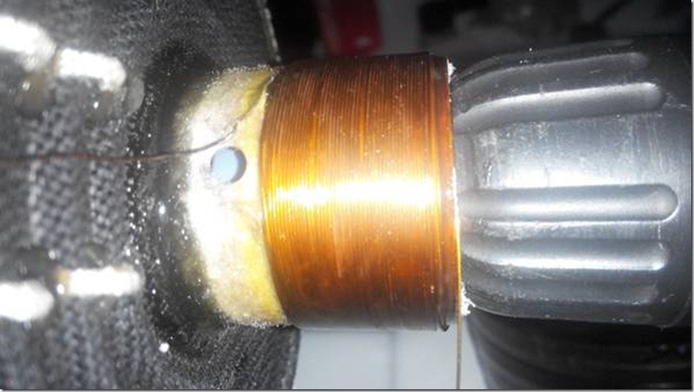
The first layer of our winding, put on a screwdriver
- After the end of winding the coil, you will need to leave it for a day to completely dry
- And if you used shellac, then the coil must be heated to 80-120 degrees (for example, in the oven)
- Shellac will not otherwise solidify
- Here is the main disadvantage when using shellac.
- But when it dries up, a certain amount of elasticity remains, which completely excludes damage to the winding from drying out of the impregnation or during its thermal expansion
- After drying, it remains to attach the diffuser to the speaker, and
- repair of car subwoofers is considered successful if everything works
To prevent the coil from rubbing against the magnetic system, we need to set a uniform circular gap:
- For this purpose, paper cut into strips is suitable.
- We insert it in a circle (where possible) between the body and the coil, thereby obtaining a uniform gap
- Check for jamming and snagging by moving the diffuser gently up and down with your hand.
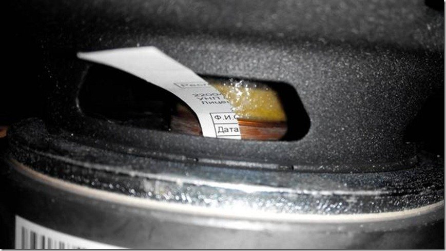
We insert pieces of paper between the coil and the body
- Then we glue the suspension of our speaker and carefully insert it into place
- Give the details time to dry
- Then you can pull out the centering papers
- Check again for sticking
- When everything is in order, put a layer of glue
- We dry and put the finished subwoofer in the car for checking
- Do not forget to lower the volume by half.
- Subwoofer rewind complete
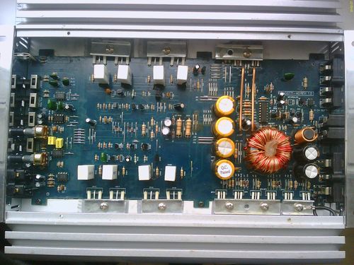
The device is almost the same, except that the dimensions are larger, microcircuits, or capacitors can be in a different order:
- Let's take a closer look at the voltage converter, power supply and amplifier.
- The ceratec subwoofer amplifier is usually two-channel, but two channels are connected to one single dynamic head
- Moreover, each channel in the amplifier amplifies a different sound frequency, low and medium, as a rule
- In addition, modern amplifiers, almost all, operate on one microcircuit from the TDA series.
- To get more power at the amplifier output, twelve volts from the on-board network of the car is not enough, for powerful microcircuits the supply voltage is from 40 volts
- Therefore, in the subwoofer circuit b w there is a built-in high-frequency converter that converts the voltage of 12 volts into the necessary for normal operation of the amplifier
- In the figure, we have divided the entire scheme into three main blocks. A1 - equalizer control, it breaks down extremely rarely, you need to try to break it, we will not devote time to it, it changes entirely
- A2 is a voltage converter, and A3 is a power amplifier.Let's dwell on A2 and A3 in more detail
Slightly enlarged diagram
- The voltage, through the filter, comes to the capacitor C1, from there it is fed to the transistor switches VT1 and VT2
- Transistor keys are controlled by a high frequency signal generated by the DD1 microcircuit
- The amplified signal from the transistors VT1-VT2 comes to the transformer T1, where the voltage turns from 12V to 40 Volts
- Moreover, the secondary winding of the transformer consists of two windings, a rectifier consisting of two diodes is used for rectification
- To unload these diodes, two more diodes are installed in parallel.
- Each of the DD2 and DD3 microcircuits is powered only by its own diodes
- To smooth out high-frequency pulses, capacitors are installed, C2 and C3 are marked.
- Converter A2 ends at this point, then comes the power amplifier A3
- Modern amplifiers consist of a single microcircuit
- At its input, in order to obtain normal output parameters, a signal of a certain magnitude must be present
- The designers of this subwoofer decided that not every car radio would have enough power, or rather the strength of the output signal from the primary amplifier, in order to obtain the nominal output parameters.
- Therefore, a transistor was added to amplify the signal before the input of the microcircuit, on the DD2 and DD3 circuit
- Here is a list of the main radio components that fail most often.
- It happens that for the replacement of one capacitor the price in the workshop will be considerable, but the work is penny
- Therefore, it is better to check the entire scheme yourself before paying without looking.
Additionally, I recommend that you study the repair video.
Good day, dear pikabushniki! This post will tell you how to fix a subwoofer if, for no reason at all, it starts to buzz.
Our dear pikabushnik turned to me with a request “The bufik buzzed, can you fix it?”
One of the main concerns in all amplifiers is noise control. Most often they struggle with interference from a 220 volt network. In a network of 50 Hz, this is exactly 50 Hz and is a network low-frequency interference. Basically, they fight with her as a hindrance, she then buzzes in the speakers. One of the ways how to “overcome” (significantly reduce) is to put “large” smoothing capacities in the power supply circuit. Most often, in transistor / integrated circuits, in the event of such noise, there is a faulty power smoothing capacitor.
We remove the radiator and see that one of the containers not only swelled (in the photo on the right), but also tore off the contact pad.
It is better to replace the capacitors with a pair, so that due to the capacitance of the capacitors that has changed over time, you do not catch power interference.
It turned out that the capacitor was also depressurized, and the electrolyte dirtied the board.
Instead of the used capacitors of the "SamXon" trademark, it was decided to put the capacitors, which have not yet let me down "ECAP".
We wash off the oxides with alcohol and seal them.
Since the “new” capacitors have a little narrower output contacts, they do not fit tightly on the board, that's okay. The pins have been bent and the capacitors sit tightly in place. The subwoofer is at home and no strong vibration effects on the capacitors will be affected, they can be left without epoxy gluing. We collect, check, everything works without noise.
Car subwoofer speaker repair is a rather laborious process, but not very difficult. Watching the video will help you quickly deal with this issue.
For the experiment, an old Mystery subwoofer was used. After a breakdown occurred, or rather the deliberate burning of the speaker with the help of an amplified distorted signal, it was disassembled with the removal of the diffuser.
1. For this it was necessary to soften the glue, which is the bonding base of most parts of the speaker. The softening of the glue occurs under the influence of a solvent, which is applied using a syringe with a needle.
2. After the solvent had acted, all parts, in particular the dust cap, were carefully separated from each other.
3. Further from the speaker basket, the upper suspension of the diffuser and the centering washer of the lower suspension were disconnected (again by impregnating the glue line with a solvent).
4. Then, the coil is wound on the blank in two layers with a thin wire. The coil frame was an empty cylindrical aluminum can.
The burned-out speaker coil was wound with a wire of a different cross-section, but close in parameters.The native cross-section of the wire was 0.45 mm, and was used with a cross-section of 0.40 mm.
After the subwoofer was assembled, its work was restored.
The video is not considered a difficult case, almost any DIY can handle such work.
I got the Kics speaker for free, but the problem was that the coil was scorched even though it was playing. Without hesitation, I decided what to do and set myself. First of all, I pasted the speaker for the sake of interest. The autopsy was done with acetone and a knife.
Soaked the diffuser and washer, then slowly peeled it off. The coil was all black and smelled very unpleasant.
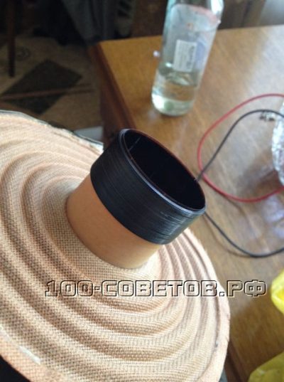
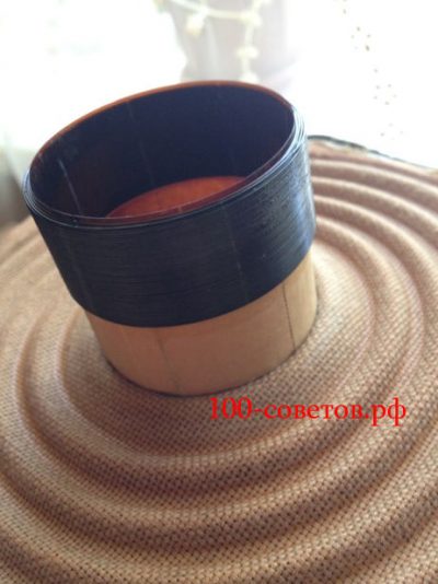

I thought that I would rewind myself, but it became lazy. We found a "master" who rewound it for me, but I was not happy for long. After 3 days, the coil flew off.
The reason is the so-called "master" did not allow the glue to dry normally, and did not warm up the coil (after impregnation with BF-2 glue, it is necessary to warm up the coil for 2-3 hours at a temperature of 120-140 degrees). It was a shame, because I laid the wires, bought the amplifier, but there was no sense.
The second time he did not dare to carry him, because he rewound his friend 3 times and the coil flew off all the time.
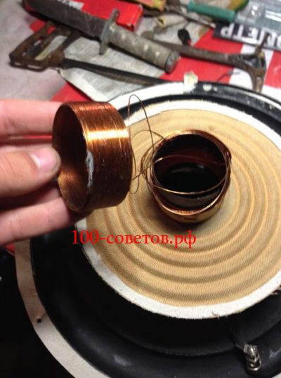
As a result, I realized that I needed to wind myself. The thickness of the standard wire is 0.40, I found only 0.35, from some kind of transformer. I wound it completely by hand, impregnated it with EDP with epoxy glue (I know that it is not quite the right solution, but I did not find BF-2 in our city).
It turned out to lay 4 layers not too even, the resistance instead of 4 ohms became 5.6 ohms. He centered the speaker in the following sequence: glued the diffuser, then connected the amplifier, and through the program reproduced frequencies from 10 Hz to 40 Hz while gluing the centering washer.
He made sure that nothing was rubbed anywhere, and left to dry for a day.
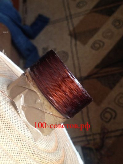
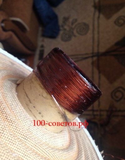

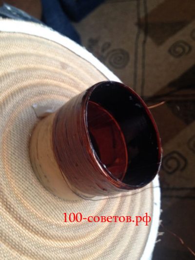

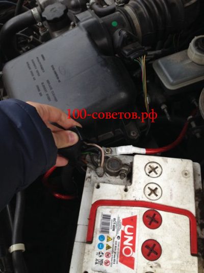
The wires are crimped into the lugs, I also additionally threw a wire from the generator so that the drawdowns are less.
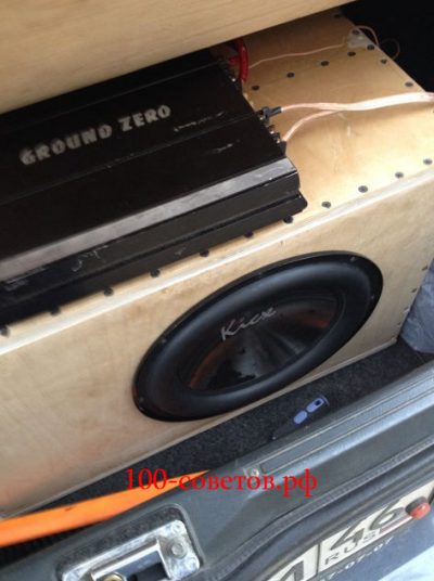
Connected to the car

The article deals with a relatively simple case of restoration of the speaker coil: without the need to make a new base for the coil (the aluminum base is well preserved); due to the considerable power of the speaker, an enamel wire of impressive cross-section is used, which is easy to lay.
To rewind the speaker coil, we need the following basic tools and tools:
- Cylindrical, all-metal mandrel (blank), for installation inside the bobbin frame during the winding process.
- BF-2 glue. Moment glue. Acetone. Ethanol.
- Enameled wire (enameled wire) of a certain length and section, for the manufacture of a new coil winding.
- Winding machine.
- Calipers.
- Electric soldering iron.

Bottle 100 ml with BF-2 glue.
One rewind of the coil consumes no more than 10 ml.

Aluminum (continuous) mandrel.
The outer diameter is 49.5 +/- 0.05 mm. The inner hole diameter is 8 mm. The length is about 60 mm.


IEK KU 09-18 coil (24V) as a source of winding wire.
Before winding, the wire must be properly straightened and rewound to another storage coil that has a round shape.
Most of the dynamic heads are not intended for their disassembly and are, as it were, disposable (non-separable, unsuitable for repair) components of acoustic systems. In practice, it is often possible to successfully disassemble a speaker of a typical design and reassemble it. The main task is to soften the glue, with the help of which many component parts of the speaker are held together, and separate them from each other without injury or deformation.
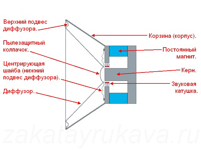
Speaker device.


The speaker mounting screws are hex slotted (photo left).
Subwoofer without speaker (photo on the right).


Subwoofer speaker (before repair).

The speaker is marked "10P32", probably indicating a 10 "diameter and 3.2 ohm impedance.
The sequence of operations is as follows.
First, we solder the flexible braided conductors (current leads) from the socket on the speaker basket.
Secondly, remove the dust cap. To do this, impregnate the glue seam with acetone (for example, with a syringe with a needle), use the tip of a knife to separate the cap from the diffuser. Based on the results of this operation, a conclusion should be drawn about the quality of the softening of the glue with acetone, and the need to use some other solvent.


Removing the dust cap.
Thirdly, we detach the upper suspension of the diffuser from the basket by saturating the glue line with a solvent. In the case of repairing a subwoofer speaker with a durable rubber suspension, the task is greatly simplified.

Disconnecting the upper suspension of the cone from the speaker basket.
Fourth, we very carefully separate the centering washer of the lower suspension of the diffuser from the speaker basket. To do this, abundantly saturate the glue seam with solvent, wait a few minutes, and slowly, using a small flat screwdriver, separate the washer from the basket.

Disconnecting the centering washer (lower cone suspension) from the speaker basket.
The diffuser should now be free to slide out of the basket. There is no need to peel off the centering washer from the diffuser.

The diffuser is marked “YC-246A”.
We assess the state of the electromagnetic system of the speaker: coil, permanent magnet. In our case, the native coil of the SVEN speaker, wound with a round copper enamel wire, had a deplorable appearance: the enamel blackened from excessive heating, several extreme loops unsticked, the coil easily unwinds (the glue is completely burnt out). Most likely, this was due to the failure of the power amplifier of the subwoofer. The conclusion is obvious - a complete replacement of the coil wire is necessary.


The condition of the old voice coil. The aluminum frame was not damaged.
A simple way to determine the required length of a new wire with sufficient accuracy is to calculate the length of one turn (knowing its radius), multiply by the number of turns in a layer and by the number of layers. SVEN subwoofer speaker has a four-layer coil with 34 turns in each layer. According to measurements, the outer diameter of the burnt coil is 53 mm, therefore, the length of one turn (at the maximum, on the surface of the coil) is: 53 x 3.14 = 166.42 mm. We multiply this length by the total number of turns in the coil: 166.42 x 34 x 4 = 22633.12 mm. Thus, having rounded up (adding a small margin), we need at least 23 meters of enameled wire to rewind the coil.


The outer and inner diameters of the burned-out coil are 53 and 50 mm, respectively (measurements are approximate due to the presence of winding deformations).
The diameter of the wire is determined using a micrometer or vernier caliper. The circular cross-sectional area is calculated according to the well-known formula: S = Pi x R 2, where R is the radius of the wire. It is necessary to measure the diameter of the wire both for copper (with stripped varnish insulation) and for insulation (the outer diameter of the future coil is also important for us). To remove the insulating varnish from the wire, when measuring the diameter on copper, it is necessary to heat the tip of the wire to red (burn the varnish) and remove the combustion products with a solvent. According to the measurement results, the burned-out coil of the subwoofer speaker was wound with a wire with a diameter of 0.38 mm over copper (section 0.113 sq. Mm) and 0.44 mm over varnish. Now a very difficult task lies ahead - to find the same, or very close, wire. If you can't buy the wire you want, you can rewind it from an electronic device. For example, as donors of enamel wires, coils of electromagnetic contactors (starters) have proven themselves well. Depending on the voltage and type of contactor, wire of different cross-sections and lengths is used in their coils.

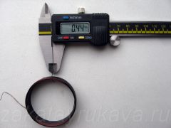

The diameter of the wire of the burnt coil.
For copper - 0.38 mm (photo on the left); on varnish - 0.44 mm (photo on the right).


Wire diameter for new winding.
For copper - 0.35 mm (photo on the left); on varnish - 0.40 mm (photo on the right).
If, as a result of a long search, it was not possible to find the original wire, then you can use a wire of a different section, with the recalculation of the number of turns, layers and coil resistance. It must be remembered that changing the wire cross-section also changes the characteristics of the dynamic head, as well as the magnetic gap and the winding height.Before making a decision on the use of a "foreign" wire in the coil winding, it is necessary to accurately calculate the geometric and electrical parameters of the future coil, to predict the operation of the dynamic head with new parameters in the acoustic system.
| Video (click to play). |
To rewind the speaker coil from the SVEN subwoofer, we managed to find a wire similar in parameters (0.35 mm in diameter for copper, 0.40 for varnish) in the coil KU 09-18 (24V) of the IEK contactor. The length of the wire in the coil of the contactor was almost twice the required value.

