In detail: diagram of atx 350 pnr no attendant do-it-yourself repair from a real master for the site my.housecope.com.
Banned
Posts: 503
Warnings: 1
Posts: 1232
>> Not enough, according to the manual she has up to 20V power supply, try to supply it from outside.
So this is the starting point, then it must power itself.
>> And also check the protective zener diode between + 5Vsb and ground
The output is about 70 ohms - the resistance of the ballast resistor. There is no zener diode, you confused it with InWin.
Warnings: 1
Posts: 1232
Well, the sounded 8.5 volts can be attributed to the not too high speed of the measuring device. He is trying to start, which means that the threshold of 9 volts is reached.
I got it all the same. D1 rang in both directions, but only when heated. Upon cooling, the effect disappeared.
Thanks to all.
If your computer's power supply fails, do not rush to get upset, as practice shows, in most cases, repairs can be done on your own. Before proceeding directly to the methodology, we will consider the block diagram of the power supply unit and provide a list of possible malfunctions, this will greatly simplify the task.
The figure shows an image of a block diagram typical for pulsed power supplies of system units.

Indicated designations:
- A - power filter unit;
- B - low-frequency rectifier with a smoothing filter;
- C - cascade of the auxiliary converter;
- D - rectifier;
- E - control unit;
- F - PWM controller;
- G - cascade of the main converter;
- H - high-frequency rectifier equipped with a smoothing filter;
- J - PSU cooling system (fan);
- L - output voltage control unit;
- K - overload protection.
- + 5_SB - standby power supply;
- P.G. - information signal, sometimes referred to as PWR_OK (required to start the motherboard);
- PS_On - signal controlling the start of the power supply unit.
| Video (click to play). |
To carry out repairs, we also need to know the pinout of the main power connector, it is shown below.

To start the power supply, it is necessary to connect the green wire (PS_ON #) to any zero black wire. This can be done using a conventional jumper. Note that for some devices the color coding may differ from the standard one, as a rule, unknown manufacturers from China are guilty of this.
It should be warned that turning on impulse power supplies without load will significantly reduce their service life and may even cause damage. Therefore, we recommend assembling a simple block of loads, its diagram is shown in the figure.

It is advisable to assemble the circuit on resistors of the PEV-10 brand, their ratings: R1 - 10 Ohm, R2 and R3 - 3.3 Ohm, R4 and R5 - 1.2 Ohm. Cooling for resistors can be made from an aluminum channel.
It is undesirable to connect a motherboard as a load during diagnostics or, as some "craftsmen" advise, an HDD and CD drive, since a faulty power supply unit can damage them.
Let's list the most common malfunctions characteristic of pulsed power supplies of system units:
- the mains fuse blows;
- + 5_SB (standby voltage) is absent, as well as more or less than the permissible;
- the voltage at the output of the power supply (+12 V, +5 V, 3.3 V) is abnormal or absent;
- no P.G. signal (PW_OK);
- PSU does not turn on remotely;
- the cooling fan does not rotate.
After the power supply is removed from the system unit and disassembled, first of all, it is necessary to inspect for the detection of damaged elements (darkening, changed color, violation of integrity). Note that in most cases, replacing a burnt-out part will not solve the problem; a piping check will be required.

If these are not found, we proceed to the following algorithm of actions:
If a faulty transistor is found, then before soldering a new one, it is necessary to test its entire strapping, consisting of diodes, low-resistance resistances and electrolytic capacitors. We recommend changing the latter to new ones with a large capacity. A good result is obtained by shunting electrolytes using 0.1 μF ceramic capacitors;
- Checking the output diode assemblies (Schottky diodes) with a multimeter, as practice shows, the most typical malfunction for them is a short circuit;

- checking the output capacitors of the electrolytic type. As a rule, their malfunction can be detected by visual inspection. It manifests itself in the form of a change in the geometry of the housing of the radio component, as well as traces from the flow of electrolyte.
It is not uncommon for an outwardly normal capacitor to be unsuitable during testing. Therefore, it is better to test them with a multimeter that has a capacitance measurement function, or use a special device for this.
Video: correct repair of an ATX power supply. <>
Note that non-working output capacitors are the most common malfunction in computer power supplies. In 80% of cases, after replacing them, the power supply unit's performance is restored;

- the resistance is measured between the outputs and zero, for +5, +12, -5 and -12 volts this indicator should be in the range from 100 to 250 ohms, and for +3.3 V in the range of 5-15 ohms.
In conclusion, we will give some tips for improving the power supply unit, which will make it work more stable:
- in many inexpensive blocks, manufacturers install rectifier diodes for two amperes, they should be replaced with more powerful ones (4-8 amperes);
- Schottky diodes on channels +5 and +3.3 volts can also be supplied more powerful, but at the same time they must have an allowable voltage, the same or greater;
- it is advisable to change the output electrolytic capacitors to new ones with a capacity of 2200-3300 uF and a rated voltage of at least 25 volts;
- it happens that instead of a diode assembly, diodes soldered to each other are installed on the +12 volt channel, it is advisable to replace them with an MBR20100 Schottky diode or similar;
- if capacities of 1 μF are installed in the piping of key transistors, replace them with 4.7-10 μF, calculated for a voltage of 50 volts.
Such a minor revision will significantly extend the life of the computer power supply.
Very interesting to read:
In the modern world, the development and obsolescence of personal computer components occurs very quickly. At the same time, one of the main components of a PC - an ATX power supply - is practically has not changed its design for the last 15 years.
Consequently, the power supply unit of both the ultra-modern gaming computer and the old office PC work on the same principle and have common troubleshooting techniques.

A typical ATX power supply circuit is shown in the figure. Structurally, it is a classic pulse unit on the TL494 PWM controller, which is triggered by a PS-ON (Power Switch On) signal from the motherboard. The rest of the time, until the PS-ON pin is pulled to ground, only the Standby Supply with a voltage of +5 V at the output is active.
Let's take a closer look at the structure of the ATX power supply. Its first element is
mains rectifier:

Its task is to convert AC from the mains to DC to power the PWM controller and the standby power supply. Structurally, it consists of the following elements:
- Fuse F1 protects the wiring and the power supply itself from overload in the event of a power supply failure, leading to a sharp increase in current consumption and, as a result, to a critical increase in temperature that can lead to a fire.
- A protective thermistor is installed in the "neutral" circuit, which reduces the current surge when the power supply unit is connected to the network.
- Next, a noise filter is installed, consisting of several chokes (L1, L2), capacitors (C1, C2, C3, C4) and a counter-winding choke Tr1... The need for such a filter is due to the significant level of interference that the impulse unit transmits to the power supply network - this interference is not only captured by television and radio receivers, but in some cases can also lead to incorrect operation of sensitive equipment.
- A diode bridge is installed behind the filter, which converts alternating current into pulsating direct current. The ripple is smoothed out by a capacitive-inductive filter.
Further, a constant voltage, present all the time the ATX power supply is connected to the outlet, goes to the control circuits of the PWM controller and the standby power supply.

Standby power supply - this is a low-power independent pulse converter based on the T11 transistor, which generates pulses, through an isolation transformer and a half-wave rectifier on the D24 diode, supplying a low-power integrated voltage regulator on the 7805 microcircuit. high voltage drop across the 7805 regulator, which under heavy load leads to overheating. For this reason, damage to the circuits powered from the standby source can lead to its failure and the subsequent impossibility of turning on the computer.
The basis of the pulse converter is PWM controller... This abbreviation has already been mentioned several times, but has not been deciphered. PWM is pulse width modulation, that is, the change in the duration of voltage pulses at their constant amplitude and frequency. The task of the PWM unit, based on the specialized TL494 microcircuit or its functional analogs, is to convert the constant voltage into pulses of the appropriate frequency, which, after the isolation transformer, are smoothed by the output filters. The voltage stabilization at the output of the pulse converter is carried out by adjusting the duration of the pulses generated by the PWM controller.
An important advantage of such a voltage conversion circuit is also the ability to work with frequencies significantly higher than 50 Hz of the mains. The higher the current frequency, the smaller the dimensions of the transformer core and the number of winding turns are required. That is why switching power supplies are much more compact and lighter than classic circuits with an input step-down transformer.

A circuit based on the T9 transistor and the following stages is responsible for turning on the ATX power supply. At the moment the power supply is switched on to the network, a voltage of 5V is supplied to the base of the transistor through the current-limiting resistor R58 from the output of the standby power supply, at the moment the PS-ON wire is shorted to ground, the circuit starts the TL494 PWM controller. In this case, the failure of the standby power supply will lead to the uncertainty of the operation of the power supply startup circuit and the probable failure of switching on, which has already been mentioned.

The main load is borne by the output stages of the converter. First of all, this concerns the switching transistors T2 and T4, which are installed on aluminum heatsinks. But at high load, their heating, even with passive cooling, can be critical, so the power supplies are additionally equipped with an exhaust fan. If it fails or is very dusty, the probability of overheating of the output stage increases significantly.
Modern power supplies are increasingly using powerful MOSFET switches instead of bipolar transistors, due to the significantly lower resistance in the open state, providing a higher efficiency of the converter and therefore less demanding on cooling.
Video about the computer power supply device, its diagnostics and repair
Initially, ATX computer power supplies used a 20-pin connector (ATX 20-pin). Now it can only be found on outdated equipment.Subsequently, the increase in the power of personal computers, and therefore their energy consumption, led to the use of additional 4-pin connectors (4-pin). Subsequently, the 20-pin and 4-pin connectors were structurally combined into one 24-pin connector, and for many power supplies, a part of the connector with additional pins could be separated for compatibility with older motherboards.

The pin assignment of the connectors is standardized in the ATX form factor as follows, according to the figure (the term "controlled" refers to those pins on which the voltage appears only when the PC is turned on and is stabilized by the PWM controller):
Is your TV, radio, mobile phone or kettle broken? And you want to create a new topic about this in this forum?
First of all, think about this: imagine that your father / son / brother has an appendicitis pain and you know from the symptoms that it is just appendicitis, but there is no experience of cutting it out, as well as the tool. And you turn on your computer, access the Internet on a medical site with the question: "Help to cut out appendicitis." Do you understand the absurdity of the whole situation? Even if they answer you, it is worth considering factors such as the patient's diabetes, allergies to anesthesia and other medical nuances. I think no one does this in real life and will risk trusting the life of their loved ones with advice from the Internet.
The same is in the repair of radio equipment, although of course these are all the material benefits of modern civilization and in case of unsuccessful repairs, you can always buy a new LCD TV, cell phone, iPAD or computer. And for the repair of such equipment, at least it is necessary to have the appropriate measuring (oscilloscope, multimeter, generator, etc.) and soldering equipment (hairdryer, SMD-hot tweezers, etc.), a schematic diagram, not to mention the necessary knowledge and repair experience.
Let's consider the situation if you are a beginner / advanced radio amateur who solders all sorts of electronic gizmos and has some of the necessary tools. You create an appropriate thread on the repair forum with a short description of “patient symptoms”, ie. for example “Samsung LE40R81B TV does not turn on”. So what? Yes, there can be a lot of reasons for not switching on - from malfunctions in the power system, problems with the processor or flashing firmware in the EEPROM memory.
More advanced users can find the blackened element on the board and attach a photo to the post. However, keep in mind that you replace this radio element with the same one - it is not a fact that your equipment will work. As a rule, something caused the combustion of this element and it could “pull” a couple of other elements along with it, not to mention the fact that it is quite difficult for a non-professional to find a burned-out m / s. Plus, in modern equipment, SMD radio elements are almost universally used, soldering which with an ESPN-40 soldering iron or a Chinese 60-Watt soldering iron you risk overheating the board, peeling tracks, etc. The subsequent restoration of which will be very, very problematic.
The purpose of this post is not any PR of repair shops, but I want to convey to you that sometimes self-repair can be more expensive than taking it to a professional workshop. Although, of course, this is your money and what is better or more risky is up to you.
If you nevertheless decide that you are able to independently repair the radio equipment, then when creating a post, be sure to indicate the full name of the device, modification, year of manufacture, country of origin and other detailed information. If there is a diagram, then attach it to the post or give a link to the source. Write down how long the symptoms have been manifesting, whether there were surges in the supply voltage network, whether there was a repair before that, what was done, what was checked, voltage measurements, oscillograms, etc. From a photo of a motherboard, as a rule, there is little sense, from a photo of a motherboard taken on a mobile phone there is no sense at all.Telepaths live in other forums.
Before creating a post, be sure to use the search on the forum and on the Internet. Read the relevant topics in the subsections, perhaps your problem is typical and has already been discussed. Be sure to read the article Repair strategy
The format of your post should be as follows:
Topics with the title “Help fix the Sony TV” with the content “broken” and a couple of blurred photos of the unscrewed back cover, taken with the 7th iPhone, at night, with a resolution of 8000x6000 pixels are immediately deleted. The more information about the breakdown you put in a post, the more chances you will get a competent answer. Understand that the forum is a system of gratuitous mutual assistance in solving problems and if you are dismissive of writing your post and do not follow the above tips, then the answers to it will be appropriate, if anyone wants to answer at all. Also note that no one should answer instantly or within a day, say, no need to write after 2 hours “That no one can help”, etc. In this case, the topic will be deleted immediately.
You should make every effort to find a breakdown on your own before you get stuck and decide to go to the forum. If you outline the whole process of finding a breakdown in your topic, then the chance of getting help from a highly qualified specialist will be very great.
If you decide to take your broken equipment to the nearest workshop, but do not know where, then perhaps our online cartographic service will help you: workshops on the map (on the left, press all buttons except “Workshops”). You can leave and view user reviews for workshops.
For repairmen and workshops: you can add your services to the map. Find your object on the map from the satellite and click on it with the left mouse button. In the field “Object type:” do not forget to change to “Equipment repair”. Adding is absolutely free! All objects are checked and moderated. A discussion of the service is here.
We are talking about converting it into a laboratory IP -
It is written about the removal of secondary components, but it is not specified what exactly and whether it is necessary to remove anything from the second side of the board.
But after looking at the board, I decided to drop everything.
After analyzing the photo from the link and manipulations, we have:
when power is supplied from the network, the unit seems to work - clicks in the transformer seem to be.
and there is a voltage on the duty + 5VSB.
Only it is not 5, but 8 with a penny of volts.
In the beginning, I thought I shorted it with solder somewhere, but no, everything is fine with the board.
Before parsing, the power supply unit functioned with normal readings.
What to do next? Maybe he took off something superfluous or everything is normal?
In the last article, we looked at what action to take if we have an ATX power supply fuse in a short circuit. This means that the problem is somewhere in the high-voltage part, and we need to ring the diode bridge, output transistors, power transistor or mosfet, depending on the model of the power supply. If the fuse is intact, we can try to connect the power cord to the power supply, and turn it on with the power switch located on the back of the power supply.
And here a surprise may await us, as soon as we flip the switch, we can hear a high-frequency whistle, sometimes loud, sometimes quiet. So, if you heard this whistle, do not even try to connect the power supply for tests to the motherboard, assembly, or install such a power supply in the system unit!
The fact is that in the duty voltage circuits (duty room) there are all the same electrolytic capacitors familiar to us from the last article, which lose capacity when heated, and from old age, their ESR increases, (in Russian for abbreviated ESR) equivalent series resistance ... At the same time, visually, these capacitors may not differ in any way from the working ones, especially for small denominations.
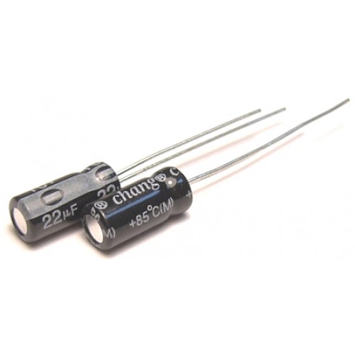
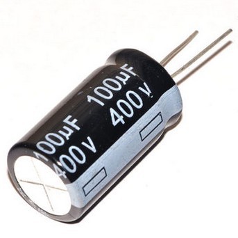

The fact is that at small denominations, manufacturers very rarely arrange notches in the upper part of an electrolytic capacitor, and they do not swell or open. Without measuring such a capacitor with a special device, it is impossible to determine the suitability of work in the circuit. Although sometimes, after soldering, we see that the gray strip on the capacitor, which marks a minus on the capacitor case, becomes dark, almost black from heating. As the repair statistics show, next to such a capacitor there is always a power semiconductor, or an output transistor, or a duty diode, or a mosfet. All these parts generate heat during operation, which adversely affects the life of electrolytic capacitors. I think it will be superfluous to explain further about the performance of such a darkened capacitor.
If the cooler of the power supply unit has stopped due to the drying out of the grease and clogging with dust, such a power supply unit will most likely require replacing almost ALL electrolytic capacitors with new ones, due to the increased temperature inside the power supply unit. The renovation will be quite dreary and not always advisable. Below is one of the common schemes on which Powerman 300-350 watt power supplies are based, it is clickable:
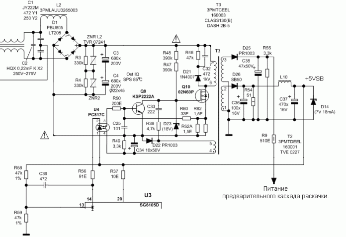
Let's take a look at which capacitors need to be changed in this circuit, in case of problems with the duty room:
So why can't we whistle a PSU to the assembly for tests? The fact is that there is one electrolytic capacitor in the duty room circuits, (highlighted in blue) with an increase in the ESR of which, we increase the duty voltage issued by the power supply to the motherboard, even before we press the power button of the system unit. In other words, as soon as we clicked the rocker switch on the back of the power supply, this voltage, which should be equal to +5 volts, goes to our power supply connector, the purple wire of the 20 Pin connector, and from there to the computer motherboard.
In my practice, there were cases when the standby voltage was equal (after removing the protective zener diode, which was in the short circuit) +8 volts, and the PWM controller was still alive. Fortunately, the power supply was of a high quality, Powerman brand, and there was a 6.2 volt protective zener diode on the + 5VSB line (as the duty room output is indicated on the diagrams).
Why is the Zener diode protective, how does it work in our case? When our voltage is less than 6.2 volts, the zener diode does not affect the operation of the circuit, but if the voltage becomes higher than 6.2 volts, our zener diode goes into a short circuit (short circuit) and connects the watchdog circuit to ground. What does it give us? The fact is that by closing the duty room to the ground, we thereby save our motherboard from supplying it with those same 8 volts, or another nominal overvoltage, along the duty room line to the motherboard, and protect the motherboard from burnout.
But this is not a 100% probability that in case of problems with capacitors, the zener diode will burn out, there is a possibility, although not very high, that it will go into a break, and thereby not protect our motherboard. In cheap power supplies, this zener diode is usually simply not installed. By the way, if you see traces of a burnt PCB on the board, you should know that most likely some semiconductor went into a short circuit there, and a very large current flowed through it, such a detail is very often the cause (though sometimes it happens that it is also a consequence) breakage.
After the voltage on the duty room returns to normal, be sure to change both capacitors at the duty room output. They may become unusable due to the supply of overvoltage to them, exceeding their nominal value. Usually there are capacitors with a nominal value of 470-1000 microfarads. If, after replacing the capacitors, we have a voltage of +5 volts on the purple wire, relative to the ground, you can short-circuit the green wire with the black one, PS-ON and GND, by starting the power supply, without the motherboard.
If at the same time the cooler starts to rotate, it means with a high degree of probability that all voltages are within the normal range, because our power supply unit started up. The next step is to verify this by measuring the voltage on the gray wire, Power Good (PG), with respect to ground. If +5 volts is present there, you are in luck, and all that remains is to measure the voltage with a multimeter at the 20 Pin power supply connector to make sure that none of them are dragged out too much.
As you can see from the table, the tolerance for +3.3, +5, +12 volts is 5%, for -5, -12 volts - 10%. If the duty room is normal, but the power supply does not start, we do not have Power Good (PG) + 5 volts, and there is zero volt on the gray wire relative to the ground, then the problem was deeper than just with the duty room. We will consider various options for breakdowns and diagnostics in such cases in the following articles. Happy repairs to everyone! AKV was with you.
Power supplies for PC - pulse. Why?
The fact is that switching power supplies, due to their technological features, are much more compact, a linear power supply of the same power would be 3 times larger and much more expensive, it has much higher efficiency, and therefore less energy loss.
To repair a power supply, you need to understand how it works:
The principle of operation of a pulsed power supply unit is very different from a linear one:
The linear power supply consists of a step-down transformer - a diode bridge - a stabilizer.
Switching power supply: 220V rectified by a diode bridge to power the generator loaded on a high-frequency transformer. The required voltage is removed from the transformer for further output.
We check the arrival of voltage - 220V on the board. If there is no voltage, we are looking for an open circuit to the board: noise suppression filter, switch, wires, or call an electrician to repair the outlet 🙂.
It is necessary to check the voltage after the mains rectifier (after the diode bridge). If there is no voltage, we check one by one:
Fuse (its resistance should be close to zero);
Varistor (possibly more than one), it is easier to check the varistor when the power supply is on - is there a current after it;
Depending on the quality of the power supply, there should be current smoothing chokes. The resistance of the ends of the choke windings should be close to zero, otherwise there is an open circuit, or just check if there is a current after them;
Diodes and a diode bridge, this circuit can be implemented with both four diodes and a solid diode bridge with four legs, diodes are very easy to check - each of them should give a very small resistance in one direction of current (
600 OM), and in the other a very large (
1.3 MOhm). The diode bridge is easiest to check when the circuit is on - if an alternating current comes to two of its legs, and a constant current does not come out to the remaining two, then it is faulty, but before turning on the circuit you need to make sure that there is no short circuit on the legs for alternating current, if any, then when turned on, the fuse will burn out and perhaps not only it.
Capacitors, you need to check for resistance, in a discharged state they should give a very small resistance, and over time it should grow and not decrease, if - but they are short - then they are faulty, and during an external examination there is a swelling or leakage of electrolyte - they lose their capacity and may have breakdowns, which means that they disrupt the operation of the circuit. With the circuit turned on, the voltage across them should be approximately 165V.
High-voltage transistors, you can check with a multimeter in the diode test mode, the base of the transistor should ring to the collector and to the emitter, but they should not be connected to each other, the polarity of the continuity of the transitions B-E and B-K depends on the structure of the transistor (pnp, npn) ... It also does not hurt to check the piping of these transistors.
If there is a generation of standby power, then we check the diodes of the output rectifiers, filtering capacitors of the secondary rectifiers, for an open key transistors.
Well, if after all the checks and actions performed, it was not possible to identify the problem, then it is already difficult to advise something here, you should check all the elements in a row.
For a more accessible explanation of this material, I highly recommend reading the article on the basics of repairing computer power supplies.
So, they gave a 350 Watt Power Man power supply unit for repair
What do we do first? Well, how is that? External and internal inspection. We look at the "offal". Are there any burnt radioelements? Maybe the board is charred somewhere or a capacitor has exploded, or it smells like burnt silicon? We take all this into account during the examination. Be sure to look at the fuse. If it burns out, then we put a temporary jumper instead of it for about the same Ampere, and then we measure the input resistance through two network wires. This can be done on the power supply plug with the "ON" button turned on. It should NOT be too small, otherwise the mains wires will be short-circuited again when the power supply is turned on.
If everything is OK, we turn on our power supply to the network using the network cable that comes with the power supply, and do not forget about the power button if you had it turned off.
Next, we measure the voltage on the purple wire
My patient showed 0 volts on the purple wire. Hmm, it really doesn’t bother. I take a multimeter and ring the purple wire to ground. Ground - these are black wires with the inscription COM. COM is short for "common", which means "common". There are also some types of, so to speak, "lands":
As soon as I touched the ground and the purple wire, my cartoon emitted a meticulous beep and showed zeros on the display. Short circuit, definitely.
Well, let's look for a circuit for this power supply. Googling through the open spaces of the Russian Internet, I still found the scheme. But I found only 300 watts on the Power Man, but they will still be similar. The differences in the circuit were only in the serial numbers of the radio components on the board. If you know how to analyze a printed circuit board for compliance with a circuit, then this does not become a big problem.
And here is a schematic diagram for Power Man 300W. Click on it to enlarge it to life size.

As we can see in the diagram, the power on duty, hereinafter referred to as the duty room, is denoted as + 5VSB:
Directly from it comes a zener diode with a nominal value of 6.3 volts to the ground. And as you remember, the Zener diode is the same diode, but it is connected in the opposite way in the circuits. The Zener diode uses the reverse branch of the I - V characteristic. If the zener diode were alive, then our + 5VSB wire would not short to ground. Most likely the zener diode has burned out and the P-N junction is destroyed.
From a physical point of view, what happens when various radio components are burned out? First, their resistance changes. For resistors, it becomes infinite, or in other words, goes into a break. In capacitors, it sometimes becomes very small, or in other words, goes into a short circuit. With semiconductors, both of these options are possible, both short circuit and open circuit.
In our case, we can check this in only one way, by removing one or both legs of the zener diode at once, as the most likely culprit of the short circuit. Next, we will check whether the short circuit has disappeared between the duty room and the mass or not. Why is this happening?
Let's remember simple tips:
1) When connected in series, the rule is greater than the larger, in other words, the total resistance of the circuit is greater than the resistance of the larger of the resistors.
2) With a parallel connection, the opposite rule works, it is less than the smaller one, in other words, the total resistance will be less than the resistance of the resistor of the smaller of the ratings.
You can take arbitrary values of the resistances of the resistors, calculate yourself and make sure of this. Let's try to think logically, if we have one of the resistances of parallel connected radio components equal to zero, what readings will we see on the multimeter screen? That's right, also equal to zero ...
And until we eliminate this short circuit by soldering one of the legs of the part that we consider to be problematic, we will not be able to determine in which part we have a short circuit.The thing is that with a sound dial, ALL parts connected in parallel with a part in a short circuit will ring with us shortly with a common wire!
Trying to remove the Zener diode. As soon as I touched it, it fell in two. No comment…
We check whether we have eliminated a short circuit in the duty room and ground circuits, or not. Indeed, the short circuit is gone. I went to the radio store for a new zener diode and soldered it. I turn on the power supply, and ... I see how my new, just bought Zener diode emits magic smoke) ...
And then I immediately remembered one of the main rules of the repairman:
If something burned out, first find the reason for this, and only then change the part to a new one, or you risk getting another burned out part.
Swearing to myself, I bite off the burned-out zener diode with side cutters, and turn on the power supply again.
Indeed, the duty room is overstated: 8.5 Volts. The main question is spinning in my head: "Is the PWM controller still alive, or have I already burned it safely?" I download the datasheet to the microcircuit and see the maximum supply voltage for the PWM controller, equal to 16 Volts. Uff, it seems like it should carry ...
I start to google about my problem on special sites dedicated to ATX PSU repair. And of course, the problem of the overvoltage of the watchman turns out to be a banal increase in the ESR of electrolytic capacitors in the watchman's circuits. We are looking for these conductors on the diagram and check them.
Remembering my assembled ESR meter
It's time to check what he is capable of.
Checking the first capacitor in the duty room circuit.
I am waiting for a value to appear on the multimeter screen, but nothing has changed.
I understand that the culprit, or at least one of the culprits of the problem, has been found. I re-solder the capacitor to exactly the same one, at face value and operating voltage, taken from the donor board of the power supply. Here I want to dwell in more detail:
If you decide to put an electrolytic capacitor into the ATX power supply not from a donor, but a new one from a store, be sure to buy LOW ESR capacitors, not ordinary ones. Conventional capacitors do not work well in high-frequency circuits, and in the power supply, just such circuits.
So, I turn on the power supply and again measure the voltage on the duty room. Taught by bitter experience, I am no longer in a hurry to put a new protective zener diode and measure the voltage on the watch room, relative to the ground. The voltage is 12 volts and a high-frequency whistle is heard.
Again I google about the problem of overestimated voltage on the duty room, and on the website rom.by, dedicated to both the repair of ATX power supplies and motherboards, and in general all computer hardware, I find my malfunction by searching in typical malfunctions of this power supply. It is recommended to replace the 10 μF capacitor.
I measure ESR on the Conder…. Ass.
The result is the same as in the first case: the device goes off scale. Some say, they say, why collect some devices, such as swollen non-working capacitors, so you can see - they are swollen, or opened with a rose
Yes, I agree with that. But this only applies to large capacitors. Relatively small capacitors do not swell. In their upper part there are no notches along which they could open. Therefore, it is simply impossible to determine their performance visually. It remains only to exchange them for knowingly workers.
So, after going through my boards, the second capacitor I needed was found on one of the donor boards. Its ESR was measured just in case. It turned out to be normal. After soldering the second capacitor into the board, I turn on the power supply with a key switch and measure the standby voltage. What was required, 5.02 volts ... Hurray!
I measure all other voltages at the power supply connector. All are correct. Operating voltage deviations less than 5%. It remains to solder the stab at 6.3 Volts. For a long time I thought why the zener diode is exactly 6.3 Volts, when the voltage of the duty room is +5 Volts? It would be more logical to put it at 5.5 volts or similar, if it stood to stabilize the voltage on the duty room.Most likely, this zener diode stands here as a protective one, so that in the event of an increase in the voltage on the duty room, above 6.3 Volts, it burns out and short-circuits the duty room circuit, thereby disconnecting the power supply and saving our motherboard from burning when it arrives at her overestimated voltage through the duty room.
The second function of this zener diode, you see, is to protect the PWM controller from overvoltage. Since the duty room is connected to the power supply of the microcircuit through a sufficiently low-resistance resistor, therefore, almost the same voltage is supplied to the 20 power leg of the PWM microcircuit as is present in our duty room.
So, what conclusions can be drawn from this repair:
1) All parts connected in parallel influence each other during measurement. Their values of active resistances are calculated according to the rule of parallel connection of resistors. In the event of a short circuit on one of the parallel connected radio components, the same short circuit will be on all other parts that are connected in parallel with this one.
2) To identify faulty capacitors, one visual inspection is not enough and it is necessary either to change all faulty electrolytic capacitors in the circuits of the problem unit of the device to known to be working ones, or to reject it by measuring with an ESR meter.
| Video (click to play). |
3) Having found any burnt part, we are not in a hurry to change it to a new one, but we are looking for the reason that led to its combustion, otherwise we risk getting another burnt part.

