In detail: the diagram of the current-measuring clamp ts4501 diagram of the do-it-yourself repair from a real master for the site my.housecope.com.
Current transformer. Current clamp. Calculation online, on-line. Do it yourself. Manufacturing. Application.
I would like to draw your attention to the fact that the voltage at the output of the current transformer will be bipolar even if a pulsating unipolar current flows in the measured circuit. The transformer cannot transmit DC voltage. It will transfer only the alternating component of the measured current to the output winding.
One more note. The secondary shunt must allow electrical current to flow in both directions. It is unacceptable to put a diode in series with the output winding. This can lead to voltage surges on this winding, transformer saturation, interference in the measured circuit, diode breakdown. You can first put a shunt resistor, and only then remove the voltage from it through the diode, or put a bridge with a shunt resistor included in its diagonal. The bridge is known to have two-way conductivity from the side of the AC voltage inputs.
To your attention a selection of materials:
TO Design of power supplies and voltage converters Development of power supplies and voltage converters. Typical schemes. Examples of finished devices. Online calculation. Possibility to ask a question to the authors
P Raktika design of electronic circuits Art of design of devices. Element base. Typical schemes. Examples of finished devices. Detailed descriptions. Online calculation. Possibility to ask a question to the authors
In some cases, it is useful to measure the sum of currents through multiple conductors. Then all these conductors are passed through the core window. The strength of the current in the secondary winding will be proportional to the strength of the sum of the currents. The direction of current flow is important. If one wire is passed so that the current flows in one direction, and the second so that the current flows in the opposite direction, then the output will be a difference in currents. As I already wrote, the current transformer works better with symmetrical measured current. In some cases, this can be achieved by running the conductors in the correct direction. For example, in a push-pull voltage converter, a current transformer can be used to limit the current. You can skip the conductors connected to the collectors (drains) of the transistors so that the current flows through the transformer in one direction, but you can pass them cross-wise, and apply the measured voltage to the bridge. Then the current transformer will work in a more gentle mode.
| Video (click to play). |
The current clamp is a conventional current transformer, only collapsible. The conductor, in which we measure the current, is passed inside the core. Then the pliers collapse, the core is closed. The handle of the current clamp contains a secondary winding wound on this collapsible core.
This clamp meter allows you to measure AC current. A slightly different principle applies to DC current measurement. Description of DC current clamp.
Look at an example of the use of a current transformer in various electronic devices:
- Laboratory switching power supply. Charger
The main "Measurement" DC current clamp - do-it-yourself attachment to the multimeter. Description
To measure large currents, as a rule, a non-contact method is used - a special current clamp.Clamp meter is a measuring device with a sliding ring, which covers the electrical wire and the value of the flowing current is displayed on the indicator of the device.
The superiority of this method is indisputable - in order to measure the current strength, there is no need to break the wire, which is especially important when measuring high currents. This article describes DC current clamp... which is quite possible to do it yourself.
To assemble the device, you need a sensitive Hall sensor, for example, UGN3503. Figure 1 shows a homemade pliers device. As already mentioned, a Hall sensor is needed, as well as a ferrite ring with a diameter of 20 to 25 mm and a large "crocodile", for example, similar to the wires for starting (lighting) a car.
The ferrite ring must be precisely and accurately sawn or broken into 2 halves. To do this, the ferrite ring must first be sawed off with a diamond file or an ampoule file. Next, sand the fracture surfaces with fine sandpaper.
On one side, glue a gasket from a drawing Whatman paper to the first half of the ferrite ring. On the other side, stick the Hall sensor on the other half of the ring. It is best to glue it with epoxy glue, only you need to make sure that the Hall sensor adheres well to the fracture zone of the ring.
The next step is to connect both halves of the ring and wrap it with a crocodile and glue it. Now, when you press the crocodile handles, the ferrite ring will open.
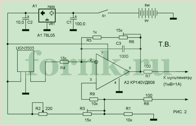
The schematic diagram of the attachment to the multimeter is shown in Figure 2. When current flows through the electric wire, a magnetic field appears around it, and the Hall sensor fixes the lines of force passing through it and generates some constant voltage at the output.
This voltage is amplified (in terms of power) of OA A1 and goes to the terminals of the multimeter. The ratio of output voltage to flowing current: 1 Ampere = 1 mVolt. Trimmers R3 and R6 are multi-turn. To configure, you need a laboratory power supply with a minimum output current of about 3A, and a built-in ammeter.
First, connect this attachment to a multimeter and set it to zero by changing the resistance R3 and the middle position of R2. Further, before any measurement, it will be necessary to set zero with potentiometer R2. Set the power supply to the lowest voltage and connect a larger load to it, for example, the light bulb used in the headlights of a car. Then hook the "pliers" onto one of the wires connected to this lamp (Figure 1).
Increase the voltage until the ammeter of the power supply unit shows 2 amperes. Tighten the resistance R6 so that the voltage value of the multimeter (in millivolts) corresponds to the ammeter data of the power supply in amperes. Check the readings a few more times by changing the amperage. By means of this attachment it is possible to measure current up to 500A.
To measure a large current, use a non-contact method - special "current clamp". This is an electronic measuring device, somewhat similar to a multimeter, with a kind of clothespin sticking out from above. This clothespin is hooked onto a wire and the current readings in this wire are observed on the screen. In short, they measure the current of the consumer - an asynchronous electric motor, water heater, electric kettle, etc. The advantages of this method are obvious - in order to measure the current, you do not need to break the circuit, which is especially important when measuring large currents.
You can make a "current clamp" for an ordinary multimeter yourself if you have a sensitive Hall sensor, for example, UGN3503. Figure 1 shows the construction of a homemade "pliers". We need, as already mentioned, a hall sensor, as well as a ferrite ring with a diameter of 20-25 mm and a large "crocodile", for example, to connect something to a car battery.The ring must be precisely and carefully broken into two halves. To do this, the ring must first be filed with a medical ampoule file. Then, treat the broken surfaces with a fine sandpaper. On one side, on one of the halves of the ring, glue a gasket made of thick paper (drawing Whatman paper). On the other side, stick the Hall sensor onto one of the halves of the ring. It is most convenient to glue it with epoxy glue, but so that the sensor fits snugly to the place where the ring is broken. Then, having folded both halves of the ring as shown in Figure 1, they must be inserted into the "crocodile's mouth" and glued to the "crocodile's jaws" with the same epoxy glue.
The result should be a structure, schematically shown in Figure 1. When you press the crocodile handles, the ferrite ring should open together with its jaws.
Now about the electronic part.
The schematic diagram of the attachment to the multimeter is shown in Figure 2. When current passes through the wire, a magnetic field appears around it, the lines of force of which penetrate the Hall sensor, and some constant voltage appears at its output. This voltage is amplified in power by the operational amplifier A1 and is fed to the input of the multimeter. Output voltage versus current: 1A = 1 mV.
Trimmer resistors R3 and R6 must be multi-turn.
To establish, you need a laboratory power supply with an output current of at least 3A, with a built-in ammeter.
First, connect the attachment to a multimeter and calibrate it to zero by adjusting R3 with R2 in the middle position. Then, before each measurement, it will be necessary to set zero with the variable resistor R2.
Set the voltage to the minimum and connect a powerful load to it, for example, a lamp from a car headlight.
Attach a "tick" to one of the wires leading to this lamp (as shown in Figure 1). Increase the voltage until the ammeter of the source shows 2-2.5A. Adjust R6 so that the multimeter reading in millivolts is equal to the ammeter reading of the source in amperes. Check the readings by changing the amperage in one direction or the other (decreasing - increasing the current and comparing with the ammeter of the source).
With this attachment, you can measure current up to 500A. For example, you can measure the current consumption of a car starter when the engine is started.
Among the tools necessary for any electrician to work, regardless of the area in which he conducts his work, the clamp meter is one of the most essential tools used every day.
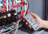
It is with the help of this tool that measurements of alternating current indicators are carried out without breaking the circuit and other important parameters of electrical networks. An important feature of this tool is that in order to measure the set parameters, there is no need to connect directly to the current-carrying conductors, it is enough to just insert the insulated wires into the inner space, between the tool clamps.
Before talking about how to use a clamp meter, you need to understand how they work. The principle of operation is based on the law of mutual induction. The operation of a clamp meter is similar to that of a transformer. The measured conductor acts as a primary winding and an alternating magnetic field is formed around it. The clamps of the device perform the function of the secondary winding of the transformer and, according to the law of mutual induction, a current is induced on them. Based on the indicators of this current, the main measured technical parameters of the current are calculated.
The main advantage of the device is the ability to measure currents without connecting the device to a break in the electrical circuit and to measure large load currents. A current clamp with a multimeter is distinguished by the fact that, in addition to the clamps themselves, they are also equipped with probes to measure the necessary parameters, for example, resistance, through direct contact with the conductor.
Almost all current clamps on the market today are digital. Let's take a closer look at how to use a clamp meter.
Let's analyze this using the example of a digital and analog device.
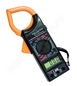
The device is professional. Consists of a digital display on liquid crystals, which reflects all measured values, a circular rotary switch. Its scale shows the main parameters of the measurement limits and their values in the desired range. The main working part of the device is the clamp itself (clamp - transformer).
The figure above shows the control panel for the M266 digital clamp meter.
And the figure below shows the supplied complete set of this device.
The device has current measurement limits - 20A, 200A and 1000A
The digital measuring clamp M266 is equipped with a multimeter with probes. They can be used to measure voltages up to 1000 Volts DC and 750 Volts AC. The device can check the health of semiconductor diodes, use the device for continuity of electrical circuits, and measure the temperature. These current clamps can also measure the insulation resistance of conductors up to 2000 megohms.
For the M266 clamp meter video, see below:
This measuring device uses the same principles of physics for measurements as digital clamps, but its functionality is slightly lower. The device has measurement limits for current - 10A, 25A, 100A, 250A and 500A, for voltage 30V and 600V, for resistance 2kOhm. But it cannot measure insulation resistance and temperature. For all other indicators, it is not inferior to a digital device.
In order to carry out a measurement with a digital clamp meter, you must perform the following operations:
- Switch on the device and set the rotary switch to the sector of the measurement limit you need;
- Bring a conductor between the magnetic-carrying transformer clamps;
- Wait until the measurement results appear on the display.
Carrying out work on measuring voltage and current in electrical networks using measuring current clamps, you must remember the following subtleties of such work:
- If the parameters displayed on the instrument panel are not correct, make sure that you have selected the correct measuring range for working with the instrument. When carrying out measurements with a pointer device, the arrow may "go off scale";
- In order for the use of the measuring device to give the most accurate results, it is recommended to use the following measurement method: take a few turns of the measured conductor in the clamp (this must be done by first de-energizing this conductor and checking the absence of voltage with the indicator), and after applying voltage, divide the measurement results by the number of turns thus, the result obtained will most accurately reflect the real operating current;
- Strictly observe all safety precautions when working with live circuits.
It is important to remember that all work on the construction and maintenance of electrical networks, as well as on electrical measurements should be carried out only by specially trained personnel who have all the necessary approvals and an order for performing work under voltage. Observe the rules of electrical safety, namely: use shoes with rubber soles (dielectric galoshes), use rubber dielectric gloves, work with a partner.
However, never forget about the danger that electric current poses to human health. And if you doubt your qualifications, stay away from electrical grids, switchboards, and electrical work. Life can be the price of a mistake here. Take care of yourself and use the services of professionals.
To measure large currents, as a rule, a non-contact method is used - a special current clamp.Clamp meter is a measuring device with a sliding ring, which covers the electrical wire and the value of the flowing current is displayed on the indicator of the device.
The superiority of this method is indisputable - in order to measure the current strength, there is no need to break the wire, which is especially important when measuring high currents. This article describes DC current clamp, which is quite possible to do it yourself.
To assemble the device, you need a sensitive Hall sensor, for example, UGN3503. Figure 1 shows a homemade pliers device. As already mentioned, a Hall sensor is needed, as well as a ferrite ring with a diameter of 20 to 25 mm and a large "crocodile", for example, similar to the wires for starting (lighting) a car.
The ferrite ring must be precisely and accurately sawn or broken into 2 halves. To do this, the ferrite ring must first be sawed off with a diamond file or an ampoule file. Next, sand the fracture surfaces with fine sandpaper.
On one side, glue a gasket from a drawing Whatman paper to the first half of the ferrite ring. On the other side, stick the Hall sensor on the other half of the ring. It is best to glue it with epoxy glue, only you need to make sure that the Hall sensor adheres well to the fracture zone of the ring.
The next step is to connect both halves of the ring and wrap it with a crocodile and glue it. Now, when you press the crocodile handles, the ferrite ring will open.
The schematic diagram of the attachment to the multimeter is shown in Figure 2. When current flows through the electric wire, a magnetic field appears around it, and the Hall sensor fixes the lines of force passing through it and generates some constant voltage at the output.
This voltage is amplified (in terms of power) of OA A1 and goes to the terminals of the multimeter. The ratio of output voltage to flowing current: 1 Ampere = 1 mVolt. Trimmers R3 and R6 are multi-turn. To configure, you need a laboratory power supply with a minimum output current of about 3A, and a built-in ammeter.
First, connect this attachment to a multimeter and set it to zero by changing the resistance R3 and the middle position of R2. Further, before any measurement, it will be necessary to set zero with potentiometer R2. Set the power supply to the lowest voltage and connect a larger load to it, for example, the light bulb used in the headlights of a car. Then hook the "pliers" onto one of the wires connected to this lamp (Figure 1).
Increase the voltage until the ammeter of the power supply unit shows 2 amperes. Twist resistance R6 so that the voltage value of the multimeter (in millivolts) corresponds to the ammeter of the power supply in amperes. Check the readings a few more times by changing the amperage. By means of this attachment it is possible to measure current up to 500A.
The most widespread are AC clamp-on ammeters, which are usually called clamp meters. They are used to quickly measure the current in a conductor without interruption and without taking it out of operation. Clamps are used in installations up to 10 kV inclusive.
The simplest AC current clamp operates on the principle of a single-turn current transformer, the primary winding of which is a bus or wire with the measured current, and the secondary multi-turn winding, to which the ammeter is connected, is wound on a split magnetic circuit (Fig. 1, a).
Rice. one.AC current clamp circuits: a - a circuit of the simplest clamp using the principle of a single-turn current transformer, b - a circuit combining a single-turn current transformer with a rectifier device, 1 - a conductor with a measured current, 2 - a split magnetic circuit, 3 - a secondary winding, 4 - a rectifier bridge, 5 - measuring device frame, 6 - shunt resistor, 7 - measurement range switch, 8 - lever
To wrap around the bus, the magnetic circuit opens like conventional pliers when the operator acts on the insulating handles or levers of the pliers.
In modern designs of clamp meters, a circuit is used that combines a current transformer with a rectifier device. In this case, the terminals of the secondary winding are connected to the electrical measuring device not directly, but through a set of shunts (Fig. 1, b).
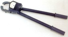
Clamps are of two types: one-handed for installations up to 1000 V and two-handed for installations from 2 to 10 kV inclusive.
Electric clamping tongs have three main parts: a working one, which includes a magnetic circuit, windings and a measuring device, an insulating one - from the working part to the stop, a handle - from stop to the end of the tongs.
With one-handed pliers, the insulating part also serves as a handle. The opening of the magnetic circuit is carried out using a pressure lever.
Rules for the use of ticks. The clamp meter can be used in closed electrical installations, as well as in open ones in dry weather. Measurements with pliers are allowed to be made both on parts covered with insulation (wire, cable, tubular fuse holder, etc.), and on bare parts (tires, etc.).
The person taking the measurement must wear dielectric gloves and stand on an insulating base. The second person should stand behind and slightly to the side of the operator and read the meter readings.
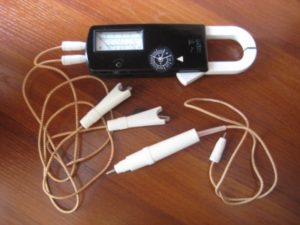
Clamp meter type Ts20 with a sliding magnetic circuit and a rectifier with a device refer to measuring current transformers. These clamps allow, when the magnetic circuit covers a conductor with an alternating current of a frequency of 50 Hz, to measure a current in the range from 0 to 600 A. an electrical measuring device is turned on.
The current measured by the device is directly proportional to the current in the conductor surrounded by the clamp and is measured on a scale in divisions from 0 to 15 if the clamp switch is set to 15, 30 or 75 A, or on the lower scale in divisions from 0 to 300 when this the switch is in position 300 (300 A).
Clamp meter type Ts20 also allows you to measure alternating voltage up to 600 V, frequency 50 Hz, for which their clamps are connected with conductors to those points of the electrical circuit between which the voltage is measured, and the lever switch is placed in the 600 V position, at which the secondary winding of the current transformer is short-circuited ...
Clamp meter: a - current, b - power
Clamp meter type D90 with a sliding ferrimagnetic magnetic circuit and a ferrodynamic device make it possible to measure active power without breaking the current circuit by covering the current conductor with them and connecting the device with two conductors with plugs to the mains voltage.
The clamps are designed to measure at two rated voltages - 220 and 380 V, frequency 50 Hz and, accordingly, three rated currents - 150, 300, 400 A or 150, 300, 500 A, which will give the corresponding nominal limits of active power measurement: 25, 50, 75 kW and 50, 100, 150 kW.
Readings within the measurement range of 25, 50, 100 kW are made on the upper scale of 0 - 50, and within the limits of 75, 150 kW - along the lower sleeper 0 - 150. Voltage switching is carried out with plugs, one of which is inserted into the generator socket marked "* ": And the other into a socket marked 220 or 380 V.
The switching of the current measurement limits is made with a lever switch, which is set to one of six positions corresponding to the values of the rated mains voltage and the rated value of the measured active power.
The D90 clamp meter can measure the active power in three-phase circuits, for which it is necessary to cover the linear wire with a magnetic circuit, and connect the voltage winding to the corresponding linear or phase voltage. In the symmetrical mode, it is enough to measure the power of one phase and multiply the measurement result by three, and in the asymmetric mode, to measure the corresponding powers one by one according to the diagrams of two or three devices and add the obtained results algebraically.
The measurement error when using electric measuring pincers of types C20 and D90 does not exceed 4% of this measurement limit at any position of the tongs themselves and of the conductor in the magnetic circuit window.
As the name implies, TC or Dietze clamp is designed to measure the strength of an alternating current in a circuit without breaking it. The operation of a current measuring instrument is based on the principle of the simplest current transformer. In this case, the primary winding is a bus or cable with a measured current, and the role of the secondary is played by the grip of the clamp, inside which there is a second multi-turn winding wound on a magnetic core made of ferromagnetic material. The alternating current in the wire (primary coil) creates an alternating magnetic mole, the lines of force of which pass through the secondary winding, exciting an EMF in it, in proportion to the value of the current in the first coil. Thus, by measuring the emerging EMF, you can find the current in the first coil (wire).
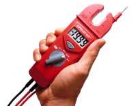
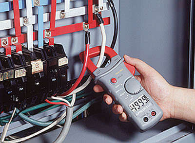
Modern clamp meters, regardless of the manufacturer and modification, contain the following elements: magnetic circuits with a movable arm bracket, a measurement range switch, a screen, output connectors for probes (in this case, the clamp can be used as a regular multimeter) and a current measurement fixation button (photo below ).
Figure 1 - ТК S-line DT 266 FT
Most modern current meters also include an internal diode bridge transformer. In this case, the terminals of the secondary winding are connected via a shunt. Depending on the range of measured currents, the current clamp can be one-handed (for voltages up to 1000 V) and two-handed with additional insulated handles (for voltages from 2 to 10 kV inclusive). Current measuring devices designed for measurements over 1 kV have an insulator length of less than 38 cm, and handles - not less than 13 cm.
As a rule, the safety category and the maximum measured current are indicated on the body of the device. For instance:
- CAT III 600 V - this means that the device is protected from short-term voltage surges inside the equipment when operating in fixed networks with voltages up to 600 V.
- CATIV 300 V - this means that the device is protected from voltage surges inside the equipment of the primary level of power supply with a voltage of up to 300 V. An example of such equipment is a conventional electric meter.
The clamp meter may only be used indoors or outdoors in dry weather. The current can be measured on both insulated and bare cables. Before use, a person must wear protective gloves, and put a dielectric base under his feet and put on special boots.
As a rule, the use of a clamp meter is not particularly difficult.Before using the tool, it is worth paying great attention to safety precautions, as mentioned earlier.
How to use the clamp meter correctly:
- Set the required range on the switch.
- Press the button for opening the magnetic circuit.
- Grasp a single conductor in an AC or DC network (if this capability is supported by the device).
- Position the current clamp perpendicular to the direction of the wire.
- Take readings from the display.
Often the difficulty in using a clamp meter lies in the selection of a single conductor: when you try to take readings from a regular cable coming from an outlet, zero should be displayed on the screen. This is because the currents of the phase conductor and the neutral conductor are equal in magnitude and opposite in direction. Consequently, the magnetic fluxes created by them are mutually compensated. If the current readings are different from zero, then this indicates the presence of a leakage current in the circuit, the value of which is equal to the obtained value. Therefore, for measurements, you need to find a place where the wires are separated and select a single core. As such a place, you can use a switchboard or the place where the phase conductor is connected to the circuit breaker. However, this cannot always be done, which limits the scope of the clamp meter.
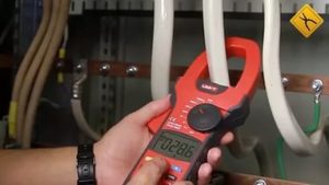
If a unit is displayed on the screen during measurements, this indicates that the current value in the wire is outside the measurement range. In this case, it is necessary to increase the range of current measurements using the switch. When taking measurements in hard-to-reach places, you can use the Hold button. With its help, you can record the result of the last measurement and see it by removing the pliers. Pressing Hold a second time will reset the value.
You can clearly see how to work with a clamp meter, you can watch the video instructions below:


