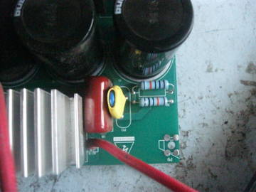
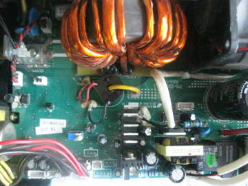
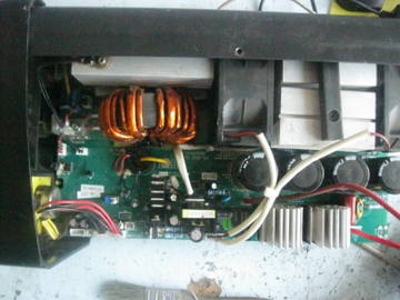
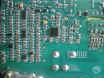
In detail: a diagram of a welding inverter fubag in 203 DIY repair from a real master for the site my.housecope.com.
Fubag in 203 is a professional inverter welding machine. A very popular model. Fubag in 203 comes to repair very often. The weakest place is the IMS module and the power supply. It is repaired in 1-4 hours, provided that before our SC the hands have not been in the device “all
- Control board
- Power section (IMS module)
- Power section (IMS module) - repair
- Management - repair
To fill out an application for the repair of the Fubag welding machine, please call: 8 (495) 215-17-22.
You fill out an online application, call the hotline +7 (495) 215-17-22, +7 (985) 999-56-96 or come to our SC.
You arrange a fence of equipment anywhere in Moscow and the region, or bring it yourself to our service centers: "Tushino", "Shchelkovskaya", "Leninsky", "Ryazansky", "Lyubertsy".
We carry out free diagnostics within 3-4 hours and report its results in any way convenient for you.
We repair equipment, test it, provide a guarantee up to 1 year.
We issue an invoice for payment by bank transfer, or you pay in cash. We provide all the necessary documents.
We deliver the equipment to the specified address, or you can pick it up yourself from any service center.
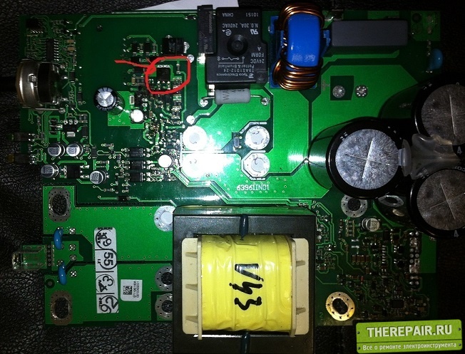
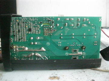
On the FUBAG IR 220 welding inverter, the PWM controller burned out and the inscription on it is not visible. From various sources in the net they advised to put the UC3843 PWM in place of the burned one. I found and put the UC3843B PWM at my own risk. ... The device turned on the thread of the lamp burns in full heat, the fans started up and the relay worked. There is no smoke or light anywhere. I measured the output voltage at all. The RJH60F7 transistors rang all intact. Powerful ohm resistors are also intact. There are no circuits for this device, therefore It is difficult to figure out why there is no voltage at the output, when everything seems to be intact, so I am asking for help in this matter.
| Video (click to play). |
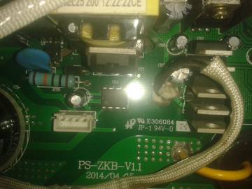
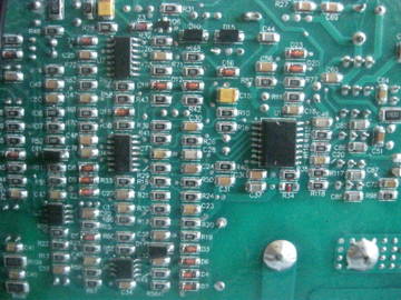
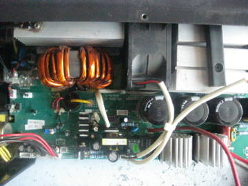
Here are my photos, I will immediately apologize for the quality, not a professional. And my question remains valid, why is there no +60 volt voltage at the output of the inverter?
Edited by Andryzel (27.06.2016 16:51:22)
The fans are spinning, the relay is triggered, everything starts smoothly, the lamp is on, the network is on, but there is no output. The power keys are all whole voltages on the conductors of almost 400 volts. It feels like there is a breakage somewhere at the output, but without a circuit I can't eat this beast. Maybe the second shim is dead. After all, I replaced UC3846 first with UC3843. Also, the zener diode burned out without a circuit, I don't know the name, it is in the base circuit of the K3878 transistor. We need a Russian analogue of a zener diode.
I agree. It's difficult without a diagram, but it's worth trying.
Maybe the second shim is dead UC3846 because the first one I replaced UC3843. The zener diode also burned out without a circuit, I do not know the name, it is in the base circuit of the K3878 transistor. We need a Russian analogue of a zener diode.
Zener diode for 18V. 1N4746A Russian analogue of КС218Ж.
Let's figure it out. Fortunately, I have the same apparatus. Tell us with what malfunction it came to you, how did this malfunction occur, what have you already done?
Edited by Andryzel (06/29/2016 06:42:12 PM)
a on L7815 +11.8 volts. It seemed a little understated
It is not normal. Strongly underestimated. You are looking in the right direction and close to the answer.
Today I changed the voltage regulator L7815 to an analogue of K142EN8, the voltage remained 11.8 volts. The direction seems to have chosen the wrong one. Power to the voltage regulator L7815 comes from the secondary winding of the transformer Tr2 through diodes. Power is also supplied to the fans from here. So where the fans are powered, it says +24 volts. Measure there +15.6. A big request to you, if you have the same welding worker, please measure how much voltage goes to the fans, where it is + 24V.
Edited by Andryzel (07/03/2016 10:55:14 PM)
Thank you for the hint. So I did, I turned on the device without a light bulb. The device started up and the output really became more + 77 volts. But my joy was not long. After driving the device for about 20 minutes at idle without load, I turned it off with a button from the mains. In general, I was 100% sure that it was possible to give the device to the owner. The device stood at work at night and in the morning I came to work and decided to check the welder again. Plugging it into the network, the device started up and soon stopped working. Having disassembled it, I began to measure the power on the UC3843B with a multimeter. The power supply showed + 7.9 volts. I think very little again, the microcircuit is out of order. I soldered the mikruhu from the board and began to check with a multimeter between the 5th and 6th legs, There is no short. Then I also measured between 5 and 7, there is also no short, then 6 and 7. In general, there is no short anywhere. Only this is not an indicator for microcircuits. But how do you know that it is intact? Then I turned on the device without a microcircuit in the network and again I measured the supply voltage of the microcircuit and was very surprised by the + 80 volt reading. I measured it on the C75 encoder (47mkfX63v), which is parallel to the microcircuit power buses. In general, I'm in a slight shock. Either the device showed it without load. Or again there is a malfunction in the microcircuit power circuit. In general, I don’t know how much + 80v should come without load. or maybe + 12V.
Thank you again for helping me. I read in the net about the UC3843B about all its functions. A smart thing is this mikruha.
In short, if, what is wrong with the diodes in the secondary circuit of the TP2 transformer, the microcircuit simply stops working and goes into protection. All the intricacies of electronics. I found the cause of all the troubles with the launch of the UC3843B was a leakage diode D25. I replaced it and everything returned to normal. The device whispered and again the joy visited me that it was not in vain.Good luck!
Edited by Andryzel (06/29/2016 11:42:12 PM)
And what is the real capacity of the C75 condenser?
Repair of welding inverters, despite its complexity, in most cases can be done independently. And if you are well versed in the design of such devices and have an idea of what is more likely to fail in them, you can successfully optimize the costs of professional service.
Replacement of radio components in the process of repairing a welding inverter
The main purpose of any inverter is to generate a constant welding current, which is obtained by rectifying a high-frequency alternating current. The use of a high-frequency alternating current, converted by means of a special inverter module from a rectified mains supply, is due to the fact that the strength of such a current can be effectively increased to the required value using a compact transformer. It is this principle underlying the operation of the inverter that allows such equipment to be compact in size with high efficiency.
Functional diagram of the welding inverter
The welding inverter circuit, which determines its technical characteristics, includes the following main elements:
- a primary rectifier unit, the basis of which is a diode bridge (the task of such a unit is to rectify an alternating current coming from a standard electrical network);
- an inverter unit, the main element of which is a transistor assembly (it is with the help of this unit that the direct current supplied to its input is converted into an alternating current, the frequency of which is 50–100 kHz);
- a high-frequency step-down transformer, on which, due to a decrease in the input voltage, the output current is significantly increased (due to the principle of high-frequency transformation, a current can be generated at the output of such a device, the strength of which reaches 200–250 A);
- output rectifier, assembled on the basis of power diodes (the task of this block of the inverter includes rectifying an alternating high-frequency current, which is necessary for performing welding).
The welding inverter circuit contains a number of other elements that improve its operation and functionality, but the main ones are the above.

