In detail: do-it-yourself electra grinder repair from a real master for the site my.housecope.com.
We have similar devices "work" for laying block parquet! I don't remember the company. EXTREMELY expensive, terribly professional 2.5 years ago, a second-hand in good condition cost something around 300 tanks: -0 (if I don’t confuse a gift of God with a cherry tree) no! only the sandpaper is changed and dust is blown away.
serg.com
I took the exact same surface grinder from a friend - I had to grind the slopes. It was quite a long time ago.
In short - the unit is really unkillable - they knew how to make equipment at that time.
The truth and no benefit from it - the ratio of productivity / weight is such that after an hour of torment I spat and picking up a hand grinder the second slope polished in half the time.
It produces mainly buzzing - as they say on Russian radio - “We drink vodka for the scent - we’re stupid and we have enough of our own.”
In short, the device is good for being placed in a museum. or to an exhibition of rarities. For this purpose, I have an adding machine lying around - I'm going to put it behind a glass on a shelf next to my Athlon when the repair comes to my office :-).
Angle grinder Mastermax MCP - 2800
The angle grinder is an essential power tool in our household use. Depending on the installation of this or that attachment to the grinder, a varied amount of work can be performed.
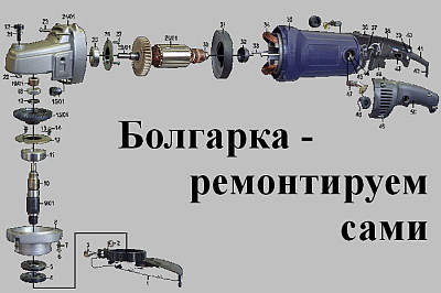
In appearance and design, such grinders are so-called grinders, consisting of such parts as:
- protective cover;
- ventilation hole;
- push button switch;
- side handle;
- spindle lock.
| Video (click to play). |
The photo shows the gearing mechanism, or in other words, the pairing of the mechanical part of the gearbox with the electric motor.
Grinder reducer and electric motor
For the mechanical part, the following are subject to wear:
I would think that giving a full explanation of the mechanical part of the gearbox simply does not make sense.
Attachments for angle grinders have a different assortment, depending also on the work carried out.
Let's concentrate our attention in Fig. 2 on the following schematic image, - the principle of operation of an electric motor.
The image of the red arrow in the figure shows the direction of the current, as it is commonly believed in the section on electrical engineering: »The current in the electrical circuit flows from the clamp source with a positive potential to the source with a negative potential. Moreover, the positive potential changes its sign to the opposite - from the resistance, which has a connection in the electrical circuit.
The electrical circuit here is closed on the collector, more precisely on the "winding - collector" contact connections for the electric motor rotor.
That is, the rotor collector through the graphite brushes in the circuit has an electrical connection.
The two stator windings of the electric motor are connected in series in an electrical circuit.
In my practice, a similar electrical connection Fig. 2 for all elements of a collector electric motor - I have not seen that a wire with one potential has a direct electrical connection to the collector through a graphite brush, and the second wire with a different potential has a series connection through two stator windings with the second graphite brush.
The simplest and most complete explanation for these electrical connections is given directly by the electrical circuit of the collector electric motor in Fig. 3.It is this connection of all elements that is typical for grinder motors, where the electrical circuit is closed on two rotor windings - in this way.
Here we can notice that the two windings of the rotor of the electric motor for this section are connected in series with each other and have a contact electrical connection "collector - brush".
The connection of the two rotor windings relative to the external source of alternating voltage is parallel.
Among the causes of malfunctions of the electric motor of the grinder, such a malfunction as wear of the graphite brushes, which are in contact friction with the collector of the electric motor, can be cited.
This part, as well as other parts for power tools, can be purchased from specialized technical departments of stores.
Diagnostics of the electric motor — grinders
Diagnostics of the electric motor of the grinder Fig. 3 should be carried out for individual sections of the electrical circuit of this circuit.
To do this, you need either an Ohmmeter device or a multimeter device. The device The multimeter is preliminarily for measuring resistance - set in the appropriate position.
To measure the resistance of two separate stator windings - one probe of the device is connected to the brush contact, the other probe of the device is connected to the corresponding pin of the electrical plug.
If this section breaks, - the device will accordingly indicate the absence of resistance.
If it works, the device will indicate the presence of resistance of one or another measured section of the electrical circuit.
By connecting two test leads of the device to two pins of the electric plug of the grinder, the display of the device will show the total resistance for:
- two stator windings;
- two rotor windings,
- that is, it will indicate the total value of the resistance.
The change in the speed of rotation of the rotor of the electric motor Fig. 4 is carried out through the following electrical circuit.
| Video (click to play). |
The electrical diagram consists of:
- resistor R1

