In detail: a stand for repairing generators with your own hands from a real master for the site my.housecope.com.
- admin on the difference between 8v and 16v controllers on the example of January 7.2 8v and Bosch 7.9.7 16v
- admin on Useful information
- admin on Atomic soft
- admin on Answered questions (comments) in the last months
- admin on Pinout of the connection block for the COURT M7.9.7. / January 7.2 to the salon wiring of the Europanel (VAZ 2114)
- admin on Chiptuning - About the CCP and BCN table (for dummies)
- admin on Answer to the question on Atomic Tune 2.8.8
- daser on Angel Eyes
- Kirill on Pinout of the connection block for the COURT M7.9.7. / January7.2 to the saloon wiring of the Europanel (VAZ 2114)
- Anonymous on the post Answered questions (comments) in the last months
Well, I'll tell you right away - to make such a stand at home is either very difficult or simply unrealistic. In short, I did not make any stand
But the idea was interesting, or so it seemed to me. Well, further in order:
I thought, why not take a set of tools, a head for 24, a drill and unscrew the generator, thereby saving myself from unnecessary installation work on the machine. In theory, everything seemed simple.
Took my toolbox 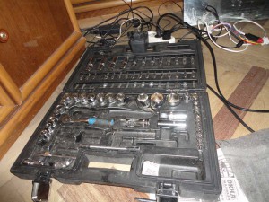
Took a drill and a head for 24

I put my head in the pulley and started to twist it

Everything is spinning super, cool, everything is kind of good ... but then I understand that I'm messing up somewhere in full, I call Mvirgo, tell me what and how, he tells me something like “you moron, without +12 on the rotor excitation windings, he will not work. at the start, +12 is supplied through the lamp from the instrument panel. " I pick up the book and figure out that yes ... I was.
+12 are fed through this connector 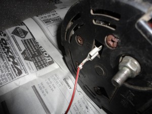
At first I wanted to bring +12 there through the adapter, but it gave out 15V. I realized that this is a lot and brought one of my batteries. it was already discharged and gave out exactly 12.14V.
Hooked up the whole thing

and tried to twist. When +12 is applied to the windings, the rotor turns very hard. Those. twisting it with a drill is unrealistic - or the drill will cover itself or something else. In general, after 2 hours of engaging in all this disgrace, I came to the conclusion that it was unrealistic to make such a stand at home and started the usual and already familiar study of the generator's intrinsicities.
Maybe especially keen visitors saw that in the last article the generator was a little strange. I noticed it right away, but decided not to write about it, as there were some misunderstandings.
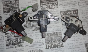
Now there are pictures of two diode bridges. 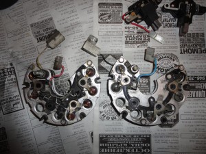
new on the left, old on the right. find the differences!
right - on the old one there are no 3 diodes, those that are responsible for supplying voltage to the windings ... Ie. it turns out that the voltage to the windings will only go through the battery charge lamp, while the light will always be on. what is wrong here? In fact, everything is simple. The old generator had a cunning voltage regulator (tablet) 8444.3702
"There are no additional diodes in the switching circuit as part of the generator set, control of the generator start-up, as well as control of its rotation frequency, is carried out directly on one of the output power windings."
This is how an ordinary system looks like and an unusual one.
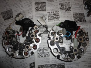
Here are the regulators themselves. I found as many as 3 different pieces 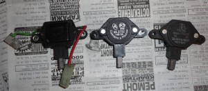
from left to right:
844.3702
55.3702
778.3702
After checking their work, I realized that 844.3702 is not working, 778.3702 is working, but somehow dumb .. I did not like it. But I liked 55.3702. I checked them by putting +12 on the contacts and looking at the voltage on the brushes.
In general, I assembled a new generator. The diode bridge rang, everything seemed to be alive.
I will try it today, I hope everything is fine.
Hello.
https://my.housecope.com/wp-content/uploads/ext/139/viewtopic.php?p=4910192#4910192
The crowds are converting the old-style generator to the new-model circuit, and as I understand it, you are the opposite.
The old-style regulator removes voltage from 3 additional. diodes, and it "drum" on the voltage on the battery, and the voltage regulator of the new sample takes readings on the battery or on consumers.
Ask why the people are trying to put the RN no.? The answer is ... in order for the battery to charge more or less normally.
"Https://my.housecope.com/wp-content/uploads/ext/139/viewtopic.php?p=4910192#4910192
The crowds are converting the old-style generator to the new-type circuit, and as I understand you, it's the other way around. "
autolada is a good forum, but with a clarification. except for the Tuning section, there is no need to do anything. Well, maybe the flood is still not bad. Having visited the sections of tens and eights a couple of times, I realized that you can go there only to neigh. There is nothing more to do there. therefore I recommend the topic Tuning.
As for the generator itself, I put a diode bridge with 9 diodes, and I threw out the six diode bridge. why ? yes, because in the article I have described it quite clearly
"There are no additional diodes in the switching circuit as part of the generator set, control of the generator start-up, as well as control of its rotation frequency, is carried out directly on one of the output power windings."
Thank you, good article, only little has been written about diode bridges, I would like to know how to put a domestic bridge on a Toyota?
Of course you can, but usually not in its pure form, but with modifications.
In the years when there were no spare parts for foreign cars by definition, they installed diodes from the legendary penny, drilling holes for them in the diode bridges of foreign cars. In some, it was possible to install Soviet diodes of general use of the D IDL series, they still drive. By the way, unlike modern diode bridges, the old ones withstood more severe overloads, including errors with battery polarity reversal. Modern bridges are much more delicate, apparently they should be protected by a fuse in the generator power circuit, which was not on old cars.
And so, everything is possible! The only thing that was difficult with was with zener diodes that keep the voltage within the specified limits. There were no Soviet ones for such currents, they were replaced with ordinary diodes, there were no problems.
And I muddied a stand at home, and a very working one, a remote control, a fan for artificial load, all the cases. works great, only the electric motor is weak, by 3 kW in total, after a load of 50 A it is inhibited (
cool
Good day! Regarding generators with a new regulator and a diode bridge without additional diodes. In general, they are characterized by a good charging voltage, I encountered only one BUT: on a taxi car, when called by a radio station, the generator voltage rose above 20 (.) Volts. After checking everything and making sure it was working, he assumed that the reason was the generator regulator, which went crazy when calling the radio station. I replaced the stock VAZ 2110 with a generator, the problem was gone!
The whim was not accidental, I met 3 more taxi cars. The replaced generators worked without any problems in a car without radio communication.
Profile
Group: Start
Posts: 2
User #: 18109
Online since: 4.09.2010
Has warnings:
(0%) 
The idea to assemble a stand for testing generators arose in my head. also add a separate check of the regulator and diode bridge to it. how to make a stand for the generator is clear, but I did not find anything for the regulator and the diode bridge. Does anyone have schemes, suggestions.
This post has been edited SKL – 27.11.2010 – 05:01
Profile
Group: Old people
Posts: 2941
User #: 809
Member since: 4/11/2005
Has warnings:
(0%)
Profile
Group: Old people
Posts: 1561
User #: 362
On the forum since: 04/10/2005
Has warnings:
(0%)
Profile
Group: Start
Posts: 2
User #: 18109
Online since: 4.09.2010
Has warnings:
(0%)
Advertisements:
“Sales from electric: XProg-m Updated. (build Peter) + Chinese update. We buy iProg USB and motoadapter. Info - iProg USB + motoadapter.
Sales from Vasilich: Calculators for iProgPro. Calculators for iProgUSB. STool - Odometer correction program.
Attention to all iProg USB owners, the update begins SUMMER 2018 ... March 12, 2009 in Crazy Pens
Register to get an account. It's simple!
To accurately determine the malfunction of the generator, in the electrical system of the car, it is enough to check the voltage regulator and tighten the belt. But basically you have to remove the generator and install it on the stand for a more accurate determination.
Basic requirement for generator testing at the stand these are brushes ground to the collector slip rings, and the rings themselves are clean.
- The image shows how to connect the generator for testing on the bench.
- 1. Voltmeter.
- 2. Toggle switch, or switch.
- 3. Ammeter.
- 4. Battery.
- 5. Rheostat.
- 6. Generator.
At the stand, turn on the electric engine, set the voltage at the generator output to 14V with a rheostat, and bring the rotor speed to 5000 rpm. In this mode, the generator must work for at least 2 minutes, then measure the current return. If the recoil force is at least 44 A, the generator is in good order. If the value is less than the specified value, this indicates that there is a problem in the stator and rotor windings, there is damage to the valves, significant wear of the brushes and slip rings.
If there is a suspicion of a malfunction of the rectifier unit valves, you should check them on a heated starter to a temperature of +20 Celsius. To warm up the generator, let it run for about 15 - 20 minutes and the rotor speed of 5000 rpm, while the voltage at the generator output should be 14V.
The most accurate way to establish the operation of the generator is possible with an oscilloscope, for this, rotate the rotor of the generator at a frequency of 1500 - 2000 rpm, feeding the excitation winding from the battery, while disconnecting the battery from terminal 30. The rectified voltage curve has a sawtooth shape, with uniform teeth, if the winding the stator and valve are in good working order.
1. Serviceable generator.
2. A punctured valve.
3. The valve circuit is open.
Also, by visual inspection, determine if there are traces of burning on the winding. The serviceability of the valves (rectifier diodes) can be checked without removing the starter from the car. The picture shows the verification method, please use it.
First, you should check if there is a short circuit on the negative and positive valves. To do this, connect the plus of the battery to terminal 30, and the minus through the control to the generator case. The lamp should not light, otherwise the negative or positive diodes have a short circuit. As shown in the picture a.
The negative valves are checked for a short circuit by connecting the plus of the battery with a plug without marking (image b), and the minus of the battery with the generator case through the lamp. If the lamp lights up, there is a short circuit in one or more valves.
The positive valves are checked as follows, the plus of the battery is connected to the terminal 30 of the generator (image c), and the minus of the battery through the control, with the plug of the output of the stator winding. If the lamp comes on, there is a short circuit.
The diagram for professionals is very simple. But it will be very useful for beginners, learners, students. It may also be needed by those who plan to engage in and promote such a type of service as repairing generators.With its help, it will be possible to check its performance.
As you can see in the design, spare parts are quite easy to find on the radio market, and then assembled in an hour.
As a result, you do not have to turn to experts in order to diagnose the health of the generator.
Added by: Alexandra Zeynalova
Added by: Sergey Kalashnikov
Probably it is better to take the electric motor from an old vacuum cleaner and make a simple speed controller.
And instead of rheostat 7, take 5 130 watt halogens in parallel through the switches, and instead of rheostat 9, a 21 watt light bulb is suitable.
The stand for testing car generators contains a base, made in the form of a table, on the tabletop of which an orientation device is installed for fastening and orienting the tested generator, a drive consisting of a V-belt transmission and an engine, a belt tension mechanism, a block of load resistors with electronic control and the ability to smoothly change load resistance, PLC-based control unit, including monitor and printer. The drive motor is located under the generator under test and is fixed to a plate under the base table top. The plate is installed with the ability to move by turning around the axis fixed on the base parallel to the axis of the engine shaft, and through the rod is connected to the nut of the belt tensioning mechanism. The belt tensioning mechanism is fixed in relation to the base and consists of a screw with a nut. The belt tensioner screw is driven by a handle. A shackle is used as a connecting rod.
Technical specifications
Motor type - Asynchronous
Engine speed, rpm 1000.3500
Installation weight, kg 210
Compound: General view, Specification
Software: Compass v10
Date: 2012-10-15
Views: 12 105
286
Composition: Assembly drawing (SB), Specification.
Composition: PZ, Specification, Sat.
Composition: VO, SB, 2 specifications, Detailing, PZ (design part)
Composition: 3D assembly, parts, drawings
Date: 2012-10-15
Views: 12 105
286
Leave a comment, a review of the work, a complaint (only specific criticism) or just thank the author.
All videos on this topic: test stand and much more. Videos for phones, smartphones, tablets on Android.
Do you like the section or this video? Share it with your friends!
How to find the required video - about it here Support the project! CARD (SBERBANK) - 427654002987381. From the author of the Auto electrician. Added 3 years. back. More details.
Stand for testing starters and alternators. Video review I will show you how the stand looks from the inside. You can do it. From the author Repair start. Added 10 mon. back. More details.
Test benches for alternators and starters. VT001 operates on a 220 Volt network. Checks generators under load. From the author Sergey Smirno. Added 5 years. back. More details.
The car will not start. The battery is empty. No charging. The generator is not working. Relay regulator. Examination. Stand. From the author Kolkhozim. Added 2 years. back. More details.
I show in general terms. details later. - my affiliate program! My group in VK. From the author Ramanych. Added 3 years. back. More details.
Completion of the project for the manufacture of a stand from scratch for testing car generators. What in the end gotos. From the author Evgeny Golov. Added 10 mon. back. More details.
Official presentation of a fundamentally new development of the GARO Group of Companies - a stand for checking what was filmed. From the author of garotrade. Added 5 years. back. More details.
Homemade stand for testing the generator. From the author Andrey Zaik. Added 3 years. back. More details.
SELF-MADE STAND FOR CHECKING GENERATORS AND STARTERS. This video describes a method for testing diode. From the author of Auto Russia. Added 1 year. back. More details.
From the author of Agro Progress. Added 11 mon. back. More details.
Description and operating principle of the stand for diagnostics of malfunctions of engine preheaters. From the author Andrey Gladka. Added 5 years. back. More details.
Stand 68 KI-968. For checking starters and alternators. Review of rarity. Happy New Year. The drive is 380 V. From the author Repair start. Added 10 mon. back. More details.
Typical set of educational equipment "Installation and adjustment of electrical equipment for enterprises and civil. From the author of NPP “Uchteh-Pr. Added 7 mon. back. More details.
If you are interested in the stand, find out the details: Russia: Ukraine: MSG MS002 COM - Stand. From the author Equipment. Added 11 mon. back. More details.
Homemade stand for testing car generators. Homemade stand for checking automobiles. From the author Arnold Vital. Added 4 years. back. More details.
From the author Andrjuxa WS. Added 6 years. back. More details.
From the author Maksim Makare. Added 3 years. back. More details.
From the author Expert R. Added 4 years. back. More details.
shows the process of installing, connecting and checking the generator on the stand for testing generators and starters. From the author of RATORSOCHI. Added 8 years. back. More details.
I decided to make a stand for testing the elements of the ignition system. Used to simulate engine speed. From the author of AvtoTechLife. Added 8 mon. back. More details.
Please add your comment or review. Your opinion is important to us!
Dear KMM, if you are quoting someone, then please give a link to the source, namely: It somehow turns out ugly - you don’t hesitate to distribute links to MOBILETRON and TRANSPO, but here it caused “difficulties”, plagiarism is straightforward.
For vovgut: I will give some clarifications regarding the use of the Zhiguli regulator as the “P-D” prefix. For more stable operation, I recommend connecting a 50-100 Ohm (2-5 watts) resistor between terminal “67” of the regulator and the negative (ground), for reliable closing of the tested regulator. The 1k resistor remains. And one more thing: the above link will also find the generator terminal assignments.
[QUOTE = autonica; 797988] Dear KMM, if you are quoting someone, then please give a link to the source, namely: It somehow turns out ugly - you don’t hesitate to distribute links to MOBILETRON and TRANSPO, but here it caused “difficulties”, plagiarism is straightforward.
It seems like I wrote it for myself, I didn’t assign it. What the original source didn’t give. Sorry.
Starter, they better, on the floor are checked.
I'll just keep silent here.
Now, briefly about the electrical part of the stand. Everything is done on the old basis, but accessible to the majority. Voltmeter and ammeter can be done on the AVR and on the same display. In the internet, you can find not bad solutions. There are also ready-made, the price is acceptable; one drawback is not suitable for current. who will be interested I will give links. And of course, equip the stand with a VRT - RC prefix or whatever I think can be implemented on the same controller. Well, and the last.This is of course my personal opinion, it is verified in practice, it is not bad to have or to implement it on the same AVR and one display an Inductance meter for checking a short circuit in the stator winding. For now, I use my VC9808 multimeter for this.
Reconstruction project of JSC Naberezhno-Chelninskoe GATP with detailed development of the TR zone, calculation and design of a hydraulic ditch lift.
2. ATP-10 reconstruction project with a detailed development of the TO and TR zone, design and calculation of a specialized 4-post electro-mechanical hoist.
3. The project "Trade and Service Complex KamAZ" for 300 comprehensively serviced vehicles per year with the development of an aggregate section and a stand for disassembly and assembly of the main gear
4. The project of reconstruction of the ATP for 200 KamAZ-6520 vehicles with detailed development of the site for the repair of the chassis, the design and calculation of the stand for checking the compressors.
5. Reconstruction project of Naberezhno-Chelninsky Automobile Center KamAZ LLC by introducing an automatic wash for trucks.
6. Reconstruction project of CJSC PF "TransTechService" with detailed development of the TP zone, design and calculation of a stand for testing generators and starters.
7. Project PATP for 250 buses with the development of a paint stand for painting attached parts
eight.ATP reconstruction project for 210 KamAZ-5511, KamAZ-65115 vehicles
With a detailed development of the aggregate section, the design and calculation of the stand for testing the hydraulic cylinders of trucks.
9. Reconstruction project of the Technical Service Station of LLC "Stary Dvor" with a detailed development of the copper section; design and calculation of a stand for the repair of radiators.
10. Reconstruction project Almetyevskoe Geodetic Department, with detailed development of the aggregate section, design and calculation of the stand for checking the operation of a truck oil pump.
11. Reconstruction project of GATP for 450 trucks with detailed development of the copper section, design and calculation of the stand for checking radiators.
12. The project of the PATP for 300 units of buses with a detailed development of the aggregate section, the design and calculation of the stand for disassembling and assembling the main gear.
13. Reconstruction project of LLC "KamAvtodor" with detailed development of the engine section and a set of devices for disassembly and assembly of diesel internal combustion engines of trucks.
14. Reconstruction project of OJSC SZMN ATC "Romashkinskoe" RNU of Leninogorsk with detailed development of the aggregate section and a specialized stand for accelerated testing of cardan shafts.
15. Reconstruction project Almetyevskoe Geodetic Department, with detailed development of the aggregate section and pneumatic stand for disassembly-assembly of the gearbox and the divider of trucks.
16. Project for the reconstruction of OJSC PAK with the development of an aggregate-mechanical section and a test bench for running-in transmission units.
17. Reconstruction project of JSC "TEF KAMAtransservice" with detailed development of the aggregate section and a stand for disassembling and assembling front axles with springs of trucks.
18. Reconstruction project of OJSC “Naberezhno-Chelninskoe GATP with detailed development of the aggregate section and the stand for testing the drive of the driving wheels of trucks.
19. Project "Trade and Service Complex KamAZ" for 300 comprehensively serviced vehicles per year with the development of an aggregate section and a stand for assembling, disassembling springs and straightening leaf springs.
20. The project of the PATP for 300 units of buses with a detailed development of the aggregate section, the design and calculation of the stand of the universal roller stand for testing the brakes of cars and buses.
Tags: How to make a stand for testing generators and starters with your own hands


I want to make a test stand for generators and starters, tell me which engine to take, how many watts, what other devices are needed for this, if anyone has a diagram or pictures, then throw a pozalnik, very good.
Vadim Generator is checked by a tester for 120 rubles.
Ekaterina textbook for universities and technical schools, edited by Kruglov. everything you need is there ..
Alina what nafik stand? ? give excitement and twist with a wrench.
I absolutely agree with you. The idea is great, I support it.
A car generator is an electrical device that supplies the on-board network of a car with electric current by converting mechanical energy into electrical energy. They come in different capacities (trucks need very powerful generators that can charge their batteries). One of the main functions of the generator is to charge the battery, which is discharged in half an hour without a generator. If the generator fails, the vehicle's electrical equipment will discharge the battery, and further engine operation will be impossible. In order to prevent such a situation, it is necessary to consider in detail the design of the generator, the causes of breakdowns and failure.


