In detail: supra sfd 110u do-it-yourself repair scheme from a real master for the site my.housecope.com.
4. Antenna connector
5. Audio output (red - right audio channel, white - left audio channel)
7. Surround left speaker (-) (Green / Black)
8. Surround left speaker (+) (Green)
9. Front left speaker (-) (White / Black)
10. Front left speaker (+) (White)
11. Front right speaker (-) (Gray / Black)
12. Front right speaker (+) (Gray)
13. Surround speaker right (-) (Purple / Black)
14. Surround right speaker (+) (Purple)
16. Power +12 when the ignition is on (+) (Red)
17. Power Antenna / To Amplifier (Blue)
18. Power supply + 12V constant / Memory of settings (+) (Yellow)
Circuit diagrams autoradio tape SUPRA SFD-110U, SFD-111U, SFD-113U
Compound: HK2001, SI4730, SC7313, TDA7384,
Schematic diagram car radio Supra SFD-105U
Compound: A2305, EW8108, SI4730, SI47XX, TDA7388
Schematic diagram car radio Supra SFD-106U, SFD-107U, SFD-109U (Chassis: NCD3033)
Main cast: A2305, SI47XX, SI4730, TDA7388, PT7313, SC75823E
Schematic diagram DVD / TV autoradio Supra SDD-3001, SDD-T3002
In SM, there is no circuit on Servo PCB
Circuit diagrams autoradio SUPRA SCD-300, SCD-200 (CD4050, CD-4050)
Compound:
SPHE8104LW
AM5888
25T80
TDA7377
AP1507-5
MD5406
TDA7312
TEF6606
BU1924
4730/4731
When performing an independent installation of a car radio belonging to the Supra brand, it must be remembered that devices of this type are intended for use exclusively in cars with a 12V DC power supply system and a minus using the car body. In other words, an attempt to install such car radios on vehicles with 24V power sources (buses, large trucks, etc.) may lead to their failure.
| Video (click to play). |
When choosing a specific place for installing the device, you should be guided by the conditions according to which the receiver is located in a horizontal position and at the same time the ventilation holes should not be blocked, providing free access of air to the inside of the multimedia device.
It is most correct to fix the supra car radio body using the standard mounting basket supplied in the factory set of the device. In turn, the basket is fixed in the technological compartment of the car dashboard with the help of special folded petals. In order to rigidly fix the device in the basket and eliminate vibration, its rear part is fixed with a special metal bracket.
Connecting a radio tape recorder is quite simple to perform with a universal ISO connector. If this connector is missing or it is revealed that its wiring does not correspond to the required values, then the supra radio tape recorder connection diagram below allows you to perform all the necessary operations without any problems, guided by the purpose and color marking of individual wires:
- 2) Subwoofer output (brown wire);
- 3) Output to the front right RCA (red wire);
- 4) Output to the front left RCA (white wire);
- 5) Output to the rear right RCA (blue wire);
- 6) Output to the rear left RCA (purple wire);
- 7) Video output (yellow wire);
- 8) Video input for rear view camera;
- 9) Input of the left channel from an external source (white wire);
- 10) Input of the right channel from an external source (red wire);
- 11) Video input (yellow wire);
- 12) Parking brake (gray wire);
- 13) Reverse (brown wire);
- 14) Antenna or amplifier control (blue wire);
- 18) Ignition (red wire);
- 19) Powered by rechargeable battery (yellow wire);
- 20) "Ground" (black wire);
- 21) turn on the backlight (orange wire).
In the above diagram, the devices that additionally participate in the operation of the car radio have the following digital designations: 1 - antenna, 15 - ignition switch, 16 - fuse box, 17 - battery.
When installing the speakers, white (+) and white / black wires (-) are connected to the front left speaker (22), gray (+) and gray / black (-) wires to the front right speaker (23), to the rear left speaker (24 ) green (+) and green / black (-) wires and to the rear right speaker (25) purple (+) and purple / black (-) wires, respectively.
All speaker wiring must be properly insulated for maximum audio clarity.
- File size: 228 Kb
- Equipment model: SUPRA SFD-110U / SFD-111U / SFD-113U
- File type: pdf
- Payment: Shareware
- File name: supra-sfd-110u.pdf
- File downloaded: 12
This means that you can download it for free if you have bonuses, or pay with electronic money or SMS.
Yes, I decided to replace the radio tape recorder in the car. I once already wrote about the cheapest radio tape recorder in the world, which I bought in my car about the last year, to amuse the bear. So - I bought myself almost exactly the same. (Since then, it has even dropped in price by a hundred rubles. Eight hundred now, or so.) What was the point, since the previous one still works? Oh, this is a complicated train of thought!
Firstly, the radio tape recorder in the stationary music complex in the workshop stopped working for me. Moreover, based on the symptoms, I decided that the amplifier was dead, and was not at all surprised - the radio tape recorder was old, lying in the garage for god knows how much, you never know what happened to it. This was the first argument.
The second argument is that the SUPR in the car has an inconveniently located SD card slot. I have it in some deepening, and the cards do not fit. With flash drives, everything is fine, but still incomplete functionality, disorder. And flash drives do not always contact well, sometimes a massive flash drive will play on a bump, the contact will go away, and that's all - start looking again where it played there ... With cards, there is no such thing. After all, the USB connector is the only weak point of such players, there is nothing else to break in them ...
In general, these two arguments prompted me to the following combination - to buy a new radio tape recorder in the car, move the radio tape recorder from the car to the workshop, move the radio tape recorder from the workshop to That Box ... Well, you know such boxes - there is something that has broken down long ago, to fix it there seems to be no need, but the time has not yet come to throw it out. (A very useful drawer in case you need some parts for something you need).
In general, since the SUPRA radio tape recorder suits me completely according to the results of work, and there is nothing cheaper in stores, I bought exactly the same, but slightly different - SUPRA SFD 100U. And there was 85U. Upgrade, then.
The difference between them is in the different location of the card slot:
... in the backlight color (red instead of blue) and the buttons are slightly different, although the principle is the same.
Fasteners, ponytails with connectors. The connector, which is nice, is a standard Euro, and not your own, as it happens. This means - you took out one, put the other on, two minutes and no these twists of yours.
Since there is no playing mechanism inside, the radio tape recorder is light and short in depth.
On the rear end, apart from a common connector and a fuse, it has a line-out and an antenna-in, as well as a hole of unknown purpose, in which there is nothing. Just a hole, it happens.
Connected the stand - it works. Red indication:
In reflected light - white in transmission:
I install it in the car, in two movements - I took it out, put it in.
Checking work. Allegedly, the spectral indicator is purely decorative, it blinks about anything.
Sound? Well, what are you talking about, the sound in the car depends on the head unit almost in the last place. In general, with standard speakers in the doors (well, to be honest, not quite regular - I did install filters and add tweeters to the broadband), without noise isolation, amplifiers, subwoofers and other tricks, the sound is always the same - that of a cheap radio tape recorder, that of an average one (I didn't buy expensive ones, I don't know). It suits me completely.
And I safely installed the removed radio tape recorder in the music center in the workshop, fortunately, again, the euro connector:
I took out one, inserted the other ... And I was convinced that it was not a nichrome thing in the radio tape recorder, but just a diode in the junction between the main and autonomous power supply struck. I'm a woodpecker! As a result, she played on standby batteries. No wonder the sound went out ...
But since you've changed it, what can you do. The diode was replaced, the radio tape recorder plays:
And the foolishly located SD card slot is now available.
And the Prolodzhi radio tape recorder, a victim of an erroneous diagnosis, again went to a dead end, until the next thread of opportunity.
_________________
It is very difficult to find a black cat in a dark room, especially if it is not there.
Confucius
_________________
It is very difficult to find a black cat in a dark room, especially if it is not there.
Confucius
Tension on the legs:
1 – 10,13
2 – 10,13
3 – 11,59
4 – 1,39
5 – 0,96
6 – 1,55
7 – 7,92
8 – 0
9 – 8,49
10 – 0
11 – 0,95
12 – 0,06
13 – 11,57
14 – 10,17
15 – 10,13
What is this green FB detail - ringing on the dial?
Washed dry, zero emotion on the display (panel).
(Power is supplied to the socket of the socket).
Hello everyone! So they gave the Pioneer radio tape recorder. The encoder did not work. I changed it from the Chinese radio tape recorder. Now everything works, only it scrolls 2 divisions faster.
How to choose the right encoder with a certain number of pulses?
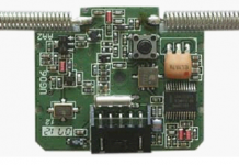
Hi all. I have in my hands a dead radio remote control from aliexpress, which has worked for a month and has finished.
the receiver burned out due to the flying out stabilizer 7v gives out. I suppose that in addition to him, both microcircuits flew out.
remote control for 10 commands (2 transmitters with 5 buttons, 1 receiver). The radio is controlled by two wires KEY1, KEY2.
it is not clear what the microcircuits are, because there is no bukafka on the cases, so, please help
1) identify microcircuits
2) write a program for the peak controller (if it is there)
or
3) come up with a new receiver circuit,
but again, the signals from the transmitters are unknown
I copied the scheme from the seal, m. somewhere a bit mistaken
Good day! I apologize if I wrote not there!
In general, I found an old Sony radio tape recorder, and in it the tda8588bj amplifier, began to google, but I did not find anything particularly suitable except for a datasheet. Can you throw the amp on it? I know that mikruha is difficult! If not, can you somehow cut off the radio board and put in the regulators? Help anyone with what they can)
SUPRA SFD-110U manual contains pages in Russian
Go to the download page for the file of this instruction: Download PDF
ATTENTION:
If the connections are not made
right, this can cause a
damage to the product, in this case
the device cannot be repaired according to
grants.
Make connections exactly
according to the scheme
connections. In case of occurrence
doubts about the correctness of the
neniya - seek advice
to the manufacturer's service center.
Insulate carefully all non-use
called wires.
The wires (and "+" and "-") going to
loudspeakers should be
insulated as from the body of a car
beel, and from a + 12V source.
Do not connect wires together,
going to the loudspeakers of different
channels.
Observe the polarity of the connection.
to the speakers.
The total impedance of the loud
thieves connected to one
the channel must be at least 4 ohms.
Do not attach a few thunder-
speakers to the output of one channel
Radio antenna power wire (C-
nii) must not be connected to circuits with
total current consumption b-
more than 100mA (0.1A). Do not connect this
wire with car body.
Make sure that in your car
the electrical system is used
with a rated voltage of +12 V
with a "minus" on the body. Otherwise
in case you need a converter.
Before making connections
turn off the power to the audio circuit
we (radio) by removing the corresponding
fuse out of the box
fuses.
Make connections according to
in accordance with the diagram presented
below.
If your car is not equipped
ISO connector, please purchase before
additionally in a car shop
strong accessories and use
ATTENTION:
Incorrect connection
If your car radio is broken, then there is a chance to repair it yourself. How and under what circumstances this can be done, my master class with a photo will tell you.
The level of complexity of modern car audio equipment is such that if it breaks down, a visit to a service center is inevitable. Replacing the processor or changing the firmware at home is an almost impossible task.
But, if only the sound has disappeared in your radio tape recorder, it is quite possible to try to repair it yourself.
As a rule, replacing a microcircuit does not cause any particular difficulties - if, of course, you are extremely careful and accurate during repairs.
First of all, we measure the voltage on the wires to which the speakers are connected with a tester - the voltage relative to the case should be in the range from 6 to 6.6 volts.Since the amplifiers in modern equipment are made in a bridge circuit, isolation capacitors are not installed at their outputs, so touching the sound output wires to ground is unacceptable.
In our case, the voltage is present, which means there is a chance that the microcircuit is intact.
We disassemble the radio tape recorder - remove the top and bottom covers. Unscrew the screws securing the disk drive located at the top.
To test the performance of the amplifier, touch the legs of the amplifier inputs with your finger. You can use a thin screwdriver or tweezers, but in this case you need to be more careful - accidental shorting of adjacent pins of the microcircuit can disable it.
The photo shows that from the row of microcircuit pins closest to us, the tracks go to the connector - these are outputs; the entrances are located in the second row.
Some models have a “Mute” button - of course, this mode must be turned off.
In our case, a background with a frequency of 50 Hz appears in the speakers - the microcircuit is operational, the malfunction is in another place.
We carefully remove the disk drive without disconnecting the wires and cables. Turn on the radio again and check the signal flow. To do this, we touch the bodies of electrolytic capacitors - there should be 4 of them near the microcircuit, according to the number of channels.
It turns out that the signal passes from the output of the microcircuit, but not from the inputs. We measure the operating mode of the microcircuit with a tester - the voltage on all legs is zero, and there is no short circuit to the case.
Next, we check the operability of the stabilizer microcircuits - two of them are highlighted in blue, they turned out to be serviceable. The third, highlighted with a red rectangle, has a zero potential at the output.
Warming up the metal protrusion of the base of the case and the leads with a soldering iron, we solder the faulty stabilizer.
The marking of the microcircuit is 78M09, i.e. stabilization voltage is 9 volts. We change the microcircuit and assemble the device.
If such a microcircuit is not at hand, and you can buy it only by visiting a district or regional center, you can use the simplest 9-volt stabilizer assembled according to any scheme on one transistor for testing - you just need to remember that the collector's touch to the device case is unacceptable.
If there is a microcircuit of the KREN8A or 7809 series, the task is simplified - they can be attached to the case anywhere.
We solder the wires of the homemade stabilizer to the corresponding contacts on the board and fix them with a piece of electrical tape or tape to prevent the tracks from peeling off when the wires are moved arbitrarily.
Turn on the radio - there is sound. I warn you right away that it is not worth using the device with such a surrogate stabilizer - as soon as possible, you need to install a “native” microcircuit, because dangling paths do not adorn any apparatus.
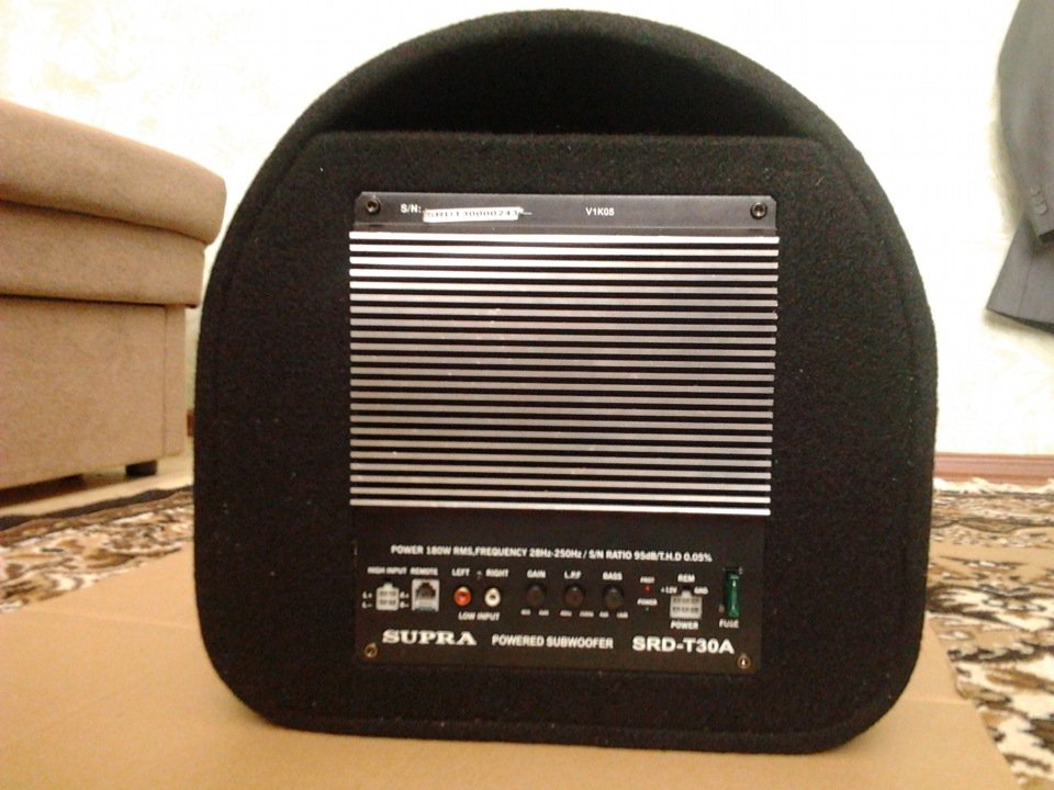
How to connect a supra subwoofer
How to connect a supra subwoofer, many are wondering. Indeed, performing such a process on your own, you can save a lot of money, which will be invested in the car in the future.
Why pay someone to do something that you can do yourself? But let's take everything in order. Connecting a subwoofer supra srd t30a is carried out according to the instructions.
Subwoofer supra srd t30 and connection
The sub is a very important element of any speaker system. Of course, the acoustics sounds good even without it, but with it the sound improves several times.
With its help, the sound of low frequencies is transferred to another level. The use of such a device is relevant for those who like big bass.
But it is not recommended to install an unsuitable buffer in the machine, as this can lead to different consequences. For example, due to constant rattling, windows will become less resistant to external influences.
Subwoofer supra srd 301 a and connection
As you know, there are three types of bass: low, medium and high.Combining them in one dynamic is simply impossible.
Therefore, if the presence of all of them is necessary, then various details are used for this. For HF, special tweeters are used that can even reproduce ultrasound. But the bass and midrange sound good only when using speakers with monolithic bass.
Installing speakers for tweeter and midrange reproduction is no problem. In the process of work, a minimum of questions may arise, so anyone can cope with this task. But installing a subwoofer is a simple matter.
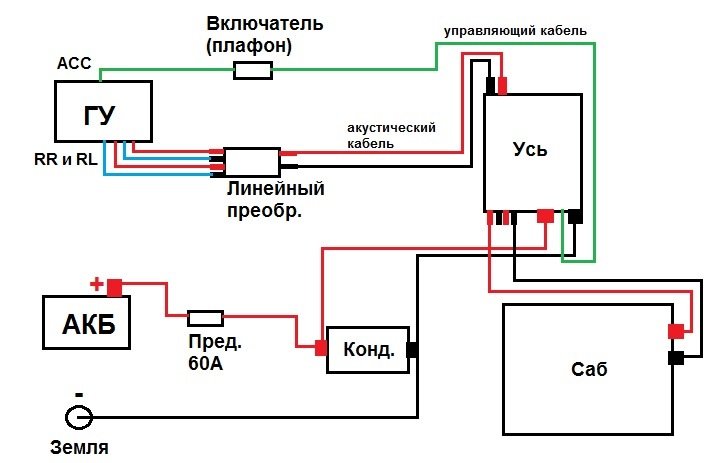
Supra subwoofer connection diagram
The main difficulty in the installation is its placement. After all, usually the speakers for low frequencies are quite large, so it is difficult to find a suitable place for it. Problems may also appear during the sound adjustment process.
There are two types of woofers on sale:
- Passive, which is most often placed in a wooden case. Due to this, the sound quality of musical compositions is significantly improved. Under no circumstances should such a device be connected directly to the speaker system.
For this, a special fuse must be used. Otherwise, a short circuit may occur in the system, as a result of which all its elements will burn out. Also, the speaker is not equipped with a built-in amplifier. Therefore, you should mount an additional one, because otherwise the sound power will be minimal.
Note: Some radios have a built-in amplifier for a subwoofer. Only in such cases can a passive subwoofer be connected directly to the unit. This process is quite complex, so to implement it, you should understand the instructions.
- The advantage of an active subwoofer is that it already has a built-in amplifier for sound. As a result, there is no need to buy an additional device (although if necessary, this can be done, since it will not interfere in any way).
Its installation is very simple. After all, it can be immediately connected to the head unit of the car. In this case, setting up a sub will include just a few simple manipulations. It's difficult to say about the cost. Since some models are more expensive, others are cheaper.
Amplifier and Subwoofer Compatibility
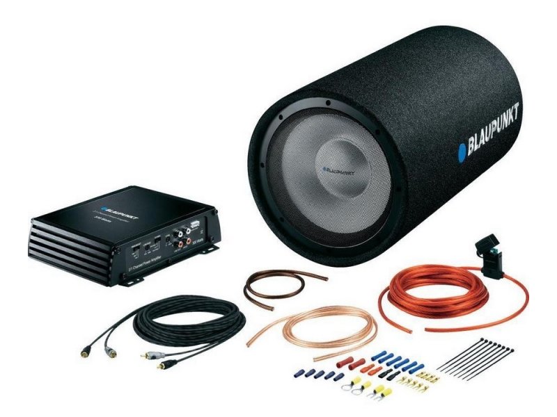
Connecting a supra subwoofer
As noted above, installing subwoofers (both active and passive) is not an easy process.
Be sure to stock up on the following materials:
- Knife. It may be needed when working with cables;
- A screwdriver for dismantling the radio;
- Adjustable wrench.
The process consists of several stages, each of which is very important:
- Remove the negative battery terminal. Otherwise, the wiring may short-circuit, and this can lead to the combustion of not only the battery, but also all devices in the car;
- The power cable must be carefully pulled from the engine compartment through the passenger compartment to the trunk, where the buffer is installed.
Note: If the hole cannot be found, it may have been masked with a rubber plug. It is used to prevent foreign particles in the form of dust and dirt from entering the passenger compartment.
- Route the speaker cable, making sure that it does not catch anywhere on anything. Otherwise, while driving, it may be slightly deformed;
- If it has already been stretched, then the next stage is its fixation. For this purpose, it is recommended to use special elastic harnesses that will securely hold the wire;
- Remove the head unit. If it is not standard, then it is not necessary to remove it. After all, factory models usually have built-in amplifiers, but purchased ones do not. Therefore, dismantling the car radio is a waste of time;
- If, nevertheless, it was decided to remove the radio tape recorder, then in this case it is recommended to look at all the connectors that are on it. Pay particular attention to the subwoofer outputs;
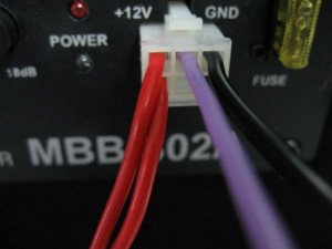
- Connect the cable through this connector. In addition, the SRC lead can be connected to the unit.It is less thick and longer. Its main task is to turn the amplifier on and off without extraneous manipulation. If this cable is not routed, then the amplifier (see Class d amplifier for subwoofer: advantages and differences from others) will not work;
- Lead the negative wire. Any black cable can be used for this purpose. Its connection should be carried out close to the subwoofer, and then it should be connected to the speaker;
- Connect all the wires, install the radio tape recorder in the standard hole;
- Install the fuse. Its importance in acoustics is very great. It protects the system from short circuits;
- Cover the floor of the cabin;
- Check if everything works fine. If any element of the speaker system does not function, you will have to disassemble it and recheck everything again.
Competent connection according to the scheme
The installation process of the sub is, of course, rather complicated. But it is quite possible to do it yourself.
Moreover, the price of such work in a car service can reach 2-3 thousand rubles. Why spend extra money? Before starting work, you should collect suitable photos for help, watch a thematic video. Our instructions won't hurt either.
Here is a schematic diagram of a SUPRA SBD-A4240 four-channel amplifier.
(To view the diagram in its original size, click on the picture. The image will open in a new window)
In the output stages of the audio frequency amplifiers (UMZCH), field-effect N-channel MOSFET transistors are used RFP50N06 or analogs.
In practice, these amplifiers instead of RFP50N06 can be used IRF60NF06, as, for example, in the copy that is in the photo. Diodes are used as double rectifier diodes D27, D28 F16A20CT (common anode), F16C20CT (common cathode).
External view of the SUPRA SBD-A4240 amplifier with the cover removed.
The output transistors of the audio frequency power amplifier (UMZCH) are MOSFET transistors IRF60NF06.
Inverter (power supply) of the Supra SBD-A4240 car amplifier. The one that converts the unipolar 12V voltage from the battery to the bipolar 23-25V required for the amplifier to work. Read more about it here.
In the photo there are 3 mosfets of one of the arms of the DC-DC converter.
Input filter block based on KIA4558 operational amplifiers.
Preamplifier stages and powerful output transistors UMZCH. Actually, these are the very 4 amplifiers. As you can see, there are four sectors on the PCB. Each sector is a separate amplifier.
The device cannot really spin the disk, something is cracking when spinning up, growls, the speed is reset. When turned off, it does not stop the disc, the tray comes out with a furiously spinning disc and this disc is scratched all over the bottom of the tray.
It turned out that the disk drive head had cracked (a circle with rubber around the edge, on the right):
Laser head, disc rotator
as a result of which the head dangled on the axis of the engine. We glue this head with something that takes plastics (acetone, dichloroethane, cyanoacrylate - which takes samples).
Due to long-term use of a player with a broken head, due to the fact that the motor was removed from under the disc, and the unstoppable disc was rapidly rotating abrading the edge of the tray, on which the disc rests with its edge after stopping, this support edge of the tray was worn off. Therefore, we glue 4 props around the perimeter:
Truncated, the device is working. The disc accelerates briskly, spins steadily, stops completely after turning off and leaves in the tray already stopped.
This player model has the following flaws: does not read mp4 - only DVD (mpeg2). At the same time, he has a USB port and he can read vob files and DVD projects from a flash drive (which is pointless, on a computer everything is in mp4 / h.264).
SUPRA SFD-110U manual contains pages in Russian
Go to the download page for the file of this instruction: Download PDF
ATTENTION:
If the connections are not made
right, this can cause a
damage to the product, in this case
the device cannot be repaired according to
grants.
Make connections exactly
according to the scheme
connections. In case of occurrence
doubts about the correctness of the
neniya - seek advice
to the manufacturer's service center.
Insulate carefully all non-use
called wires.
The wires (and "+" and "-") going to
loudspeakers should be
insulated as from the body of a car
beel, and from a + 12V source.
Do not connect wires together,
going to the loudspeakers of different
channels.
Observe the polarity of the connection.
to the speakers.
The total impedance of the loud
thieves connected to one
the channel must be at least 4 ohms.
Do not attach a few thunder-
speakers to the output of one channel
Radio antenna power wire (C-
nii) must not be connected to circuits with
total current consumption b-
more than 100mA (0.1A). Do not connect this
wire with car body.
Make sure that in your car
the electrical system is used
with a rated voltage of +12 V
with a "minus" on the body. Otherwise
in case you need a converter.
Before making connections
turn off the power to the audio circuit
we (radio) by removing the corresponding
fuse out of the box
fuses.
Make connections according to
in accordance with the diagram presented
below.
If your car is not equipped
ISO connector, please purchase before
additionally in a car shop
strong accessories and use
ATTENTION:
Incorrect connection
Single wingless


Group: Chief administrators
Posts: 7,166
Registration: 16.2.2006
From: Moscow
User #: 5
Auto: 10/96 JZA80 T67DBB 6MT, 09/00 UZS161 EUR
For Japanese versions, see the partially translated diagrams below, next to the pinouts.
For USA / Canada:
1995 TSRM - repair manual (1995), RAR archive, 67 MB
1996 Supra Resource CD - ZIP archive 41 MB
1998 Supra Resource CD - ZIP archive, 30 MB
Electrical manuals
In HTML format, also for export versions (essentially the same, differing in interface):
1995 Electical Manual - RAR archive, 25 MB
1995 Electical Manual 2 - RAR archive, 25 MB
MR (1997) Export Version OBD II:
1997 Clutch & V160.pdf - PDF 1.04 MB - Clutch & V160
1997 Manual Preface.pdf - PDF, 0.53 MB - general information and notation
1997 New Car Features.pdf - PDF, 0.4 MB - changes for 1997 model year
Air Conditioning.pdf - PDF, 0.97 MB - air conditioning
Body Electrical.pdf - PDF, 1.43 MB - body, electrical
Body Mechanical.pdf - PDF, 1.43 MB - body, mechanics
Brakes.pdf - PDF, 0.8 MB - brakes
Collision Repar.pdf - PDF, 14.4 MB - body restoration
Cooling.pdf - PDF, 0.8 MB - cooling
Diagnostics-Engine.pdf - PDF, 1.41 MB - Diagnostics - Engine
Diagnostics-Other.pdf - PDF, 2.09 MB - Diagnostics - Other
Electrical.pdf - PDF, 4.62 MB - electrical
Emmissions.pdf - PDF, 0.24 MB - Emissions Control Systems
Engine.pdf - PDF, 3.89 MB - engine (mechanics)
Ignition.pdf - PDF, 0.27 MB - ignition
Maintenance.pdf - PDF, 0.08 MB - maintenance
Owners Manual.pdf - PDF, 2.42 MB - user manual
Safety & Restraint (SRS) .pdf - PDF, 0.47 MB - Safety
SFI.pdf - PDF, 2.02 MB - Sequential Fuel Injection
Starting.pdf - PDF, 0.78 MB - Charging, engine starting system
Steering.pdf - PDF, 1.21 MB - steering system
Suspension.pdf - PDF, 2.14 MB - suspension
Torque & Service Specifications.pdf - PDF, 0.3 MB - Torques and Specifications
Turbos.pdf - PDF, 0.67 MB - turbines
Wire Harness Repair.pdf - PDF, 4.82 MB - wire harness repair
Pinouts and some diagrams:
Without VVT-i:
Pinout:
JZA80 VVT-i pinouts.xls

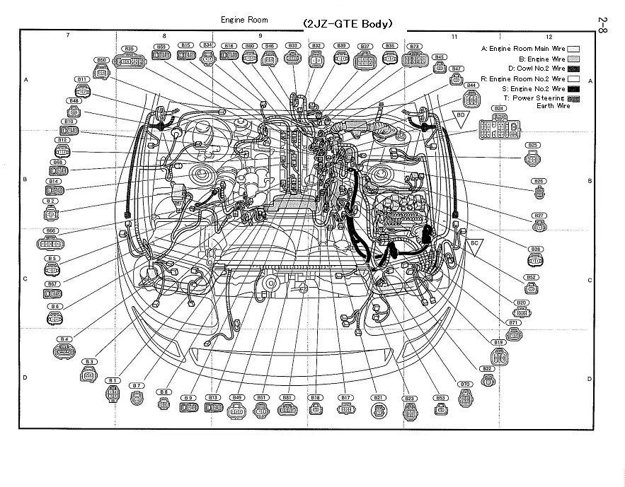
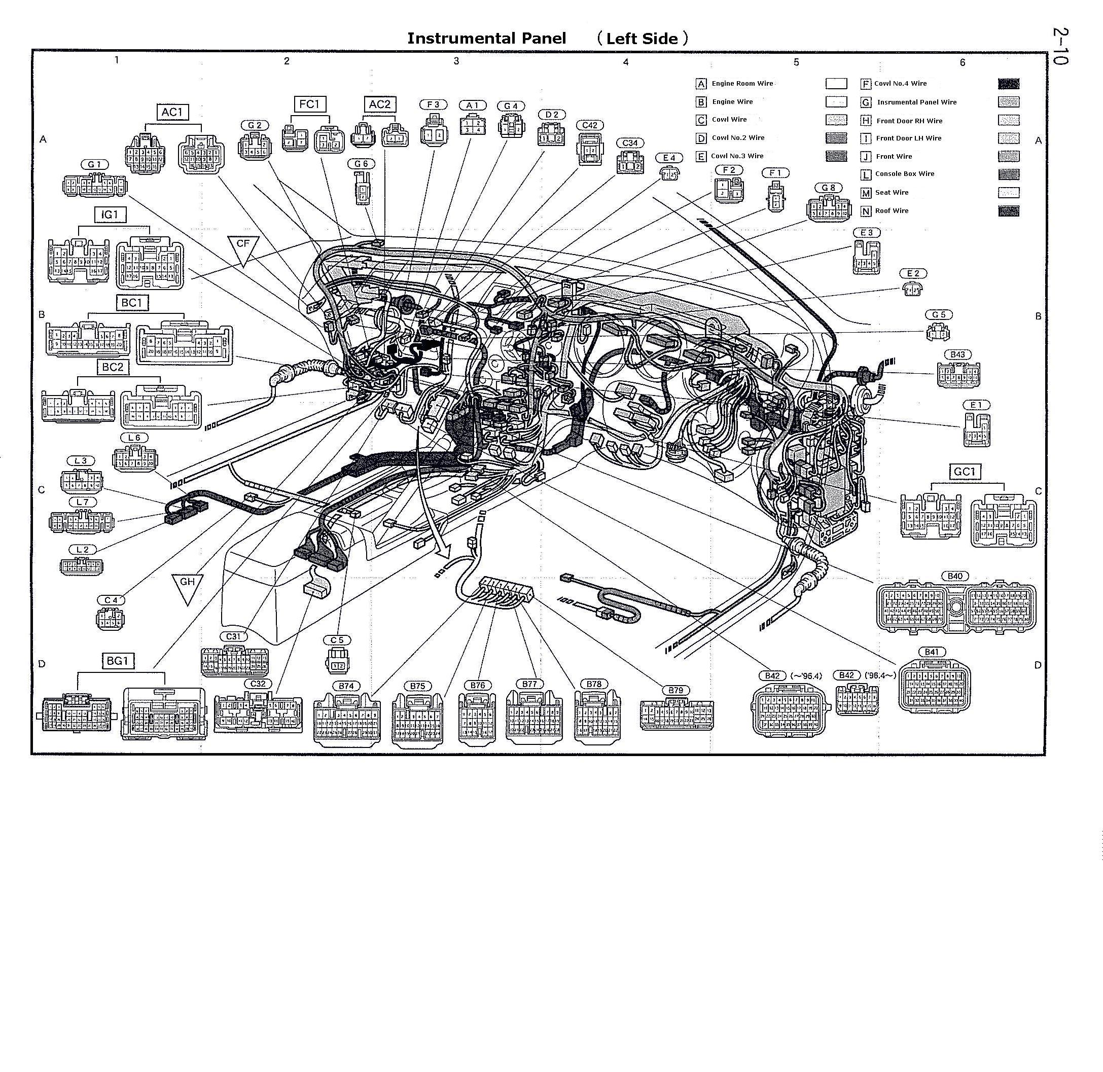

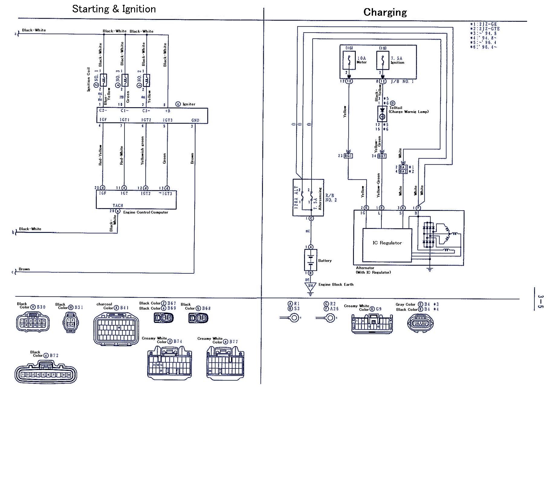

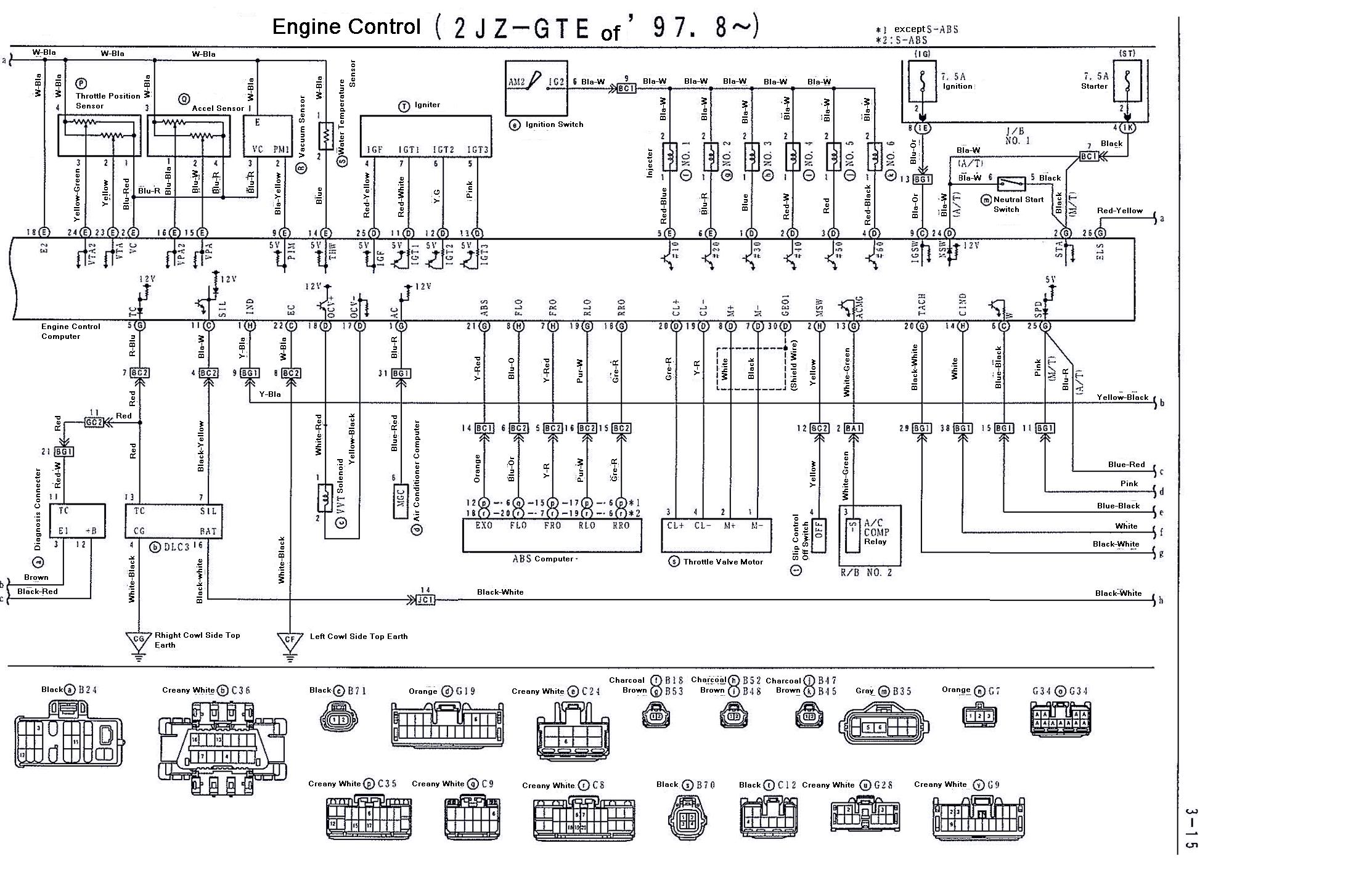

Vacuum diagram 2JZ-GTE without VVT-i
MR V160 (V161)
By Sections
All pages on one
Download link: V160 repair manual.rar - RAR archive, 6.6 MB

10/1996 ||
KYB, Michelin, Mickey Thompson, Precision, Recaro, Soara, Sound Performance, SSR, Summit, Synapse, Thermo Tec, Titan, Titek, Toyota, TRD, Trust, Walbro, Yokohama + Custom
Arguing with an admin is like fighting a dragon. It seems that he had already kicked him, and poked him with a sword, and it seems that he had settled down to sawing his throat, but then he got tired of it and he exhaled.

Message transfor »23 Jan 2016 10:45
Message funcker78 »23 Jan 2016 11:53
Message Polet-S »23 Jan 2016 14:04
Message funcker78 »23 Jan 2016 14:38
Message Samrem »23 Jan 2016 18:07
Message funcker78 »23 Jan 2016 20:25
Message Polet-S »23 Jan 2016 22:02
This is done very simply: there is an agreement with the ASC, there is a service bulletin for the warranty exchange of the assembled block motor under warranty. Further - a person with an inoperative block-motor addresses. The service-manager at the reception in the store looks at the block motor, sees that there are no obvious violations of the operating conditions, the block motor in the ASC will be replaced with a new one assembled and in cellophane, or there will be a certificate for compensation, removes a new set in packaging from sale and in a couple of days the person is given a new block-motor, closing the complaint. After, as already mentioned, either on the help of the NRP from the ASC he receives compensation, or puts a new block motor into the kit and puts it on sale again.With normal volumes in retailers, this is constantly practiced so as not to have hemorrhoids with courts and penalties, because such brands of the 2nd quality echelon as Supra, spare parts (a new block motor) can be sent for months, or a certificate can be coordinated with the vendor as well for a long time. And the time frame is strictly defined for the seller by the law on consumer protection. The warranty is over - adieu!
Message funcker78 »23 Jan 2016 23:03
Message Polet-S »24 Jan 2016 09:11
Message funcker78 »24 Jan 2016 14:25
Message funcker78 "24 Jan 2016 14:28
Message Polet-S »24 Jan 2016 18:03
Message funcker78 »24 Jan 2016 19:11
Message Polet-S »24 Jan 2016 20:56
SUPRA STV-2084E3... When you turn on the TV without a signal, such a picture is observed. The lower part of the frame is present, the upper part is absent, the separation is not clearly expressed, there is no pronounced separation strip. When a signal is applied, a normal image appears, but just above the middle of the screen, there is a black arrow-shaped stripe at the end. It turned out that the malfunction was in the frame scan output circuit, the capacitors and electrolytes of the output and feedback must be replaced.
SUPRA STV-1484 The image on the screen is sluggish (graphics are displayed normally) after two to three hours, according to the owner, it is restored. There was not enough strength to check this statement, after a day of work nothing has changed. The fault consisted in the breakdown of the LZP. After replacing it with a piece of wire, the normal operation of the TV was restored. The quality of the picture was quite satisfactory for the client.
Supra STV-2084DK When turned on, a squeak is heard coming from the power supply, the TV does not start. When checking the secondary circuits of the power supply unit, it turned out that + 12V and + 18V are normal, and instead of + 115V, only +28 - 30V. When the power was turned off from the horizontal scan, the voltage increased to + 115v. Checking the SPLIT of the transformer and its secondary circuits yielded nothing. When the scribe was connected, the voltage again sank to + 30V. I measured the pulsations on the D8075 diode with an oscilloscope and it turned out that the constant level is somewhere around + 30V, and the variable pulsations are higher. I replaced the diode, but it did not help, then I replaced the C8075 33.0x160v and everything returned to normal, the TV started up.
SUPRA STV1484DK chassis PC04 Very dark, almost invisible image, OSD behind the threshold of the tube closing. On cathodes of 220 V. Supply voltage VVU 240 V. instead of 180 c. It turned out: in the power supply circuit of pin 3 of the split tr-ra up to L804P 118 v. and cleanly, and after, at pin 3, the horizontal frequency pulses. Reason: C807S capacitance loss 47UF 160V.
SUPRA STV1484DK chassis RS04 When turned on with the network button, the TV enters standby mode and does not respond to commands from the remote control and from the front panel. It turned out that the STENDBY 12V voltage is not filtered. Reason: loss of capacitance C804S 1000 uF 16 V. After replacement, it turns on normally.
DAEWOO DMQ-1427/1457/2027/2057/2127/2157; SUPRA STV-2024; SHIVAKI STV-2012M4; NAM DMQ-2046 (Chassis: C-50); DAEWOO DTK-2053 (Chassis: C-52).
1. Tuning frequency drift. The inverter is built on the TA8701N. More often the L124 circuit is faulty (connected to pin 22), similar to the AFC circuit in AKAI CT-1407/2007 / 2107D. The built-in capacitor 47-51 pF is subject to replacement. The failure of the L125 circuit is also possible, its parameters are similar to those of L124. After replacing the capacitors, the usual procedure for sequential adjustment of the loops to the normal operation of the auto-lock system of stations.
2. Distorted, weak sound. The L128 circuit connected to the pin is guilty. 9 TA8701N. According to my data, the built-in capacitor has a nominal value of about 15 pF. We change it and tune it to the optimal sound.
SAMSUNG CK-3351/3362/5051/5314/5342/5361, SUPRA STV-2094 (Chassis: P68SA / SC), SAMSUNG CK / CW-3335/5035/5041/5081/5082/5318/5341 (Chassis: P69SA) , (Not less favorite devices of telemasters :-).
Does not keep the frequency of tuning to the TV program. These devices are built on the TDA8362 multifunctional microcircuit, which has only one tuning circuit at the IF frequency, connected to legs 2, 3 of AFC DET (T104). Again, the built-in capacitor with a capacity of about 68 pF is to blame. We change it to a hinged one and sequentially adjust the contour to normal auto-capture of stations (the setting is quite sharp).
Supra STV-20 on STR50103A - does not turn on from standby mode without warming up for 30 minutes. Change С4.7 * 50v to (+ 16v), set no more than 10.0
Supra CTV1485 MC-41A chassis, aka Goldstar GF-14/20 / 21A80 MC-41A / B. In SEKAME there is no blue color, in PAL everything is OK. In SECAMA, the blue B-Y core circuit is L504, does not react to rotation. Do not rush to change the TA8750AN microcircuit, swap the L504 and L502 circuits connected through capacitors to pins 35 and 29 of the TA8750AN. In my case, after rearranging the contours in places, everything worked, obviously, the soldering of the legs (inside) the contour affected, after which a small adjustment of the contours is required.
SUPRA STV-2084... There is a high and a sound, the picture tube is locked. After about half an hour, a picture appears. Dried C416 50.0X250V.
SUPRA STV2128... Changing the size of the raster when changing the contrast. Dried condenser 1.0x160 V in the power supply unit.
Supra STV-2017... When turned on, a characteristic squeak is heard from the power supply. After five minutes of warming up, the squeak stops. During the squeak, some programs go astray. I soldered the PSU and SR and changed the capacitors in the PSU - everything is OK.
Supra STV 2112W aka Shivaki STV-2017M4. A noteworthy defect. Came to be repaired with a broken HOT. After the replacement, by the evening when it was taken out of standby mode, the transistor was knocked out on a new one. During further repairs, an interesting feature was noticed. When switching the device to the duty room, the line does not turn off. When turned on, like in American cinema, the TV started working instantly. In standby mode for ms TDA2579V, (master) in standby mode, the supply voltage is absent. Short-circuited the ms output on the page r.-ku to ground, the lower case still works. I planted the base of the pre-exit tr-ra on the ground, one devil is working in full mode. The defect turned out to be in the 115 volt supply. Made in the same way as in the old GoldStar, two tanks, one after the diode, the second after the choke. The second was dry. The power supply of the TMS is also taken from 115, and the pickup from the line scan was enough to support the generation on the TMS.
Supra STV-2128MS and other TVs assembled on the C-50N (C-50AN) chassis, STR50103A is used as the main element of the power supply. The raster is narrowed both vertically and horizontally, at the top of the screen there is a rotation around the frame, the tuning to the channels is lost. When measuring the output voltage of the power supply, we observe a voltage of 60% of the nominal. When replacing electrolytic capacitors in the power supply unit C832, C830 (1μF / 160V), the malfunction disappears.
DAEWOO, SUPRA, ELEKTA (Chassis C-50NA) Defects manifest themselves in different ways: no start-up, narrowed screen horizontally and large vertical size, vertical twist. And there is only one malfunction - a low supply voltage of the power supply unit. Change C830, C832.
Supra STV-2900XT... No startup lowercase / no high. When measured on IC803 (7812), the input is 6 volts. It turned out that channel 12v is connected to channel 27v, and with a punctured personnel microcircuit, we have such a failure. Replace TDA3654Q.
Supra, STV-2024... No color, buzzing on sound. Unable to configure UPCHI. The inverter runs normally from the generator. Defective transistor Q503 (2SC3198) in the SYSTEM switching circuit.
Supra STV-2900XT... Fault: after replacing a burned-out 1000 pF 2000 V capacitor in the horizontal output stage, the horizontal scan does not start. When measured on IC 803 (7812), the input is 6 volts. The stabilizer output is overload. It turned out to be broken by the power supply of the TDA8145.
SUPRA STV2024 Fault: the standby mode does not light up, the TV does not turn on, there is no 103v., C453 3.3x250V breakdown on the picture tube board.
Supra STV2128... Chassis C-50N. Fault: very quiet sound. Normal operation was restored when the TA8701N IC was replaced.
SUPRA STV-2062DK (chassis C500) The main power supply is assembled on STK73410II. Fault: does not turn on from standby mode. Replace it and two litics C808 and C810.
SUPRA STV2084DK... (The scheme is typical for GOLDSTAR TVs). Fault: the screen is dark, when an accelerating voltage is added, the image appears with a strip at the top of the screen, when the + V supply voltage is added, the strip disappears, the image becomes brighter. The supply voltage of the video amplifiers has been increased to 224V instead of 180V. The C8065 47.0x160v turned out to be faulty. Along the way, I replaced the capacitor C406 1.0x160v.
| Video (click to play). |
Supra STV-2017. Fault: the raster is narrowed horizontally and vertically, a fold in the image by frames, the power supply squeals. The voltage under load drops to 70V. Defective C830 (1.0x160V)

