In detail: do-it-yourself snowmobile repair Buran from a real master for the site my.housecope.com.
Posted by Vitaly S, February 25, 2011 in Vehicles
No registered user is viewing this page.
From GAVIALL
Created Yesterday at 07:36
From Nikolay Sh
Created on June 3, 2009
From Denis
Created on August 15, 2009
From Denis
Created on August 15, 2009
From Kolobok
Created on April 17, 2012
From Your-Optic
Created Tuesday at 20:59
Dad-60 04 Feb 2012, 19:09
Andrey 051 »04 Feb 2012, 21:40
Filipych »17 Feb 2012, 14:02
A Murmansk resident wrote: the miracle of our blizzard industry, that's what he found.
Snowmobile "Buran" with your own hands.
Assemble the Buran snowmobile yourself
We offer you a complete set of parts and assemblies for self-assembly of the Buran snowmobile. The set includes all even small parts and fasteners. With only a set of wrenches in your arsenal, you can assemble a snowmobile that is superior in quality to the most demanded Russian-made snowmobile. The main advantages of a snowmobile assembled from the proposed kit-kit:
- a more high-torque and economical 4-stroke engine of the "Honda" design, made in China, modified by our company;
- Reinforced frame manufactured by Buran-chassis;
- lower cost in comparison with the original.
Moreover, all parts, except for the engine, are completely interchangeable with the parts of the Buran snowmobile, which makes it maintainable in any region of Russia.
We are ready to send the Buran snowmobile kit by a transport company to any region of the country.
| Video (click to play). |
The price of the Buran snowmobile kit is 158,000 rubles
And the revision of the "dvigi" probably consists of replacing pistons from birch to pine, aluminum connecting rods (Russian recyclable materials - to China.) And lead bearings. The life of this miracle is 300 km, in the most successful case.
Have already seen: NAH.
Filipych »17 Feb 2012, 14:20
Assenny »26 Feb 2012, 00:40
Mikhail, I am very glad for you that I have installed the heating of the handles and the trigger! And our hands are freezing! Please explain: What pens, where did you get it, how did you connect it? But no, this is a question for Buranovod.
Filipych Apr 29, 2012 6:54 pm
Dad-60 »Apr 30, 2012 7:35 am
Dyuk »01 May 2012, 11:12
Yuri Timofeevich is right. The treated pistons and cylinders did not even show any signs of wedging this year, although we drove the technique to the full as usual.
As for the modifications to the exhaust system, everything is also correct. an exhaust system with a DD resonator gives an increase of about 30%, i.e. about 43 hp removed from the engine. in terms of sound, there are two options, 4 decibels quieter (about 25%) on the driver's side and 43 hp. removed from the engine and 6 decibels quieter (about half) on the driver's side and 38 hp. remove from the engine.
Consumption drops by about 15%. The other's engine becomes with this system.
Well, and the fact that they ask to write to your personal mail, what's so strange about that? We do not like people who develop skills and realize the fruits of their labor.
Write to Yuri Timofeevich (Dad-60), he will always help.
Filipych »01 May 2012, 19:15
Filipych »01 May 2012, 19:25
Dad-60 »03 May 2012, 07:02
Filipych »03 May 2012, 22:06
Andreich »04 June 2012, 12:39
Andreich »05 June 2012, 05:32
Andreich »05 June 2012, 05:46
Andreich »06 Jun 2012, 07:08
Andreich »06 June 2012, 07:20
Andreich »19 June 2012, 11:14
Assenny »29 Jul 2012, 21:45
Hermann »04 Aug 2012, 05:28
He's set on hot. It is advisable to remove it with a native puller, which is screwed onto the thread of the flywheel, then squeezed out with a bolt, you can heat it up a little, but you can break it by the edges. Then I look at your old wiring and there is a VSA. change all the wiring to normal, and connect from the magneto to a straight line, bypassing all the crap, and take off the starter, if you don't use it, when replacing the shaft, you can not put the crown later, if, again, you do not use a starter and accumulators, I have not had it for a long time.
Filipych »05 Aug 2012, 05:21
aleks66 »11 Aug 2012, 06:57
aleks66 »11 Aug 2012, 07:07
Mishel1 »13 Aug 2012, 09:33
Starower »16 Nov 2012, 18:16
Starower »16 Nov 2012, 18:39
Mishel1 »16 Nov 2012, 20:01
Starower »20 Nov 2012, 18:08
Starower »20 Nov 2012, 18:33
finally I collected everything and when I looked around and saw that there was still a casing for the variatar. I thought I’d put it on, but I couldn’t, the resonator interfered, I didn’t want to take it off. I decided to leave the casing alone for now.
Moreover, on the advice I soldered a resistor into one of the wires of the button to turn off the engine. The blizzard started up hard, felt overflowing with fuel, raised the needle one notch and began to wind up and work normally. But I will not say anything about everything else - I don’t know. The engine sound became quieter. I want to fill up a full tank and check how long it will last. I'll unsubscribe later. Till.
Hermann »21 Nov 2012, 03:03
Time zone: UTC + 7 hours
5 How is the cable laid to prevent rollers from overturning?
Some of my thoughts have already been formulated, as the work progresses, I will spread them, but for sure the richest experience of members of the forum has already accumulated knowledge on my questions
So the questions:
1 You can remove the inner race from the shaft axis using a grinder, this is understandable, but what should be the bore diameter for the bearing on this axis (some are decently broken)?
1. The inner race is faster and easier to split. Shaft diameter = inner diameter of the bearing.
2 How to pull out the bearing cage of the scattered bearing from the balancer?
2. Turn the balance bar cheek and beat the thread - the clip should come out, another option is the puller.
3 How to disassemble the roller? It's a very difficult process, the keys are bypassed and it goes very tightly. Maybe someone came up with something?
3. Screwdriver faster however
4 How to flare the roller to remove the bearing? And then roll back? or so: how to replace the roller bearing?
4. Insert a rod with a diameter of 22 mm, prick the bearing on it. Without taking out the bar, you hammer with a hammer, you put in a new bearing. There are many options for flaring - with a ball, a sleeve ...
5 How is the cable laid to prevent rollers from overturning?
There are many ideas with photos on that forum. I personally did not bother
Some of my thoughts have already been formulated, as the work progresses, I will spread them, but for sure the richest experience of members of the forum has already accumulated knowledge on my questions


It seems to have answered all the questions. Read between the lines


So the questions:
1 You can remove the inner race from the shaft axis using a grinder, this is understandable, but what should be the bore diameter for the bearing on this axis (some are decently broken)?
1. The inner race is faster and easier to split. Shaft diameter = inner diameter of the bearing.
1.1 there are classic ways to restore the bearing seating (even rewind the foil)
2 How to pull out the bearing cage of the scattered bearing from the balancer?
2. Turn the balance bar cheek and beat the thread - the clip should come out, another option is the puller.
2.2 heat up.
3 How to disassemble the roller? It's a very difficult process, the keys are bypassed and it goes very tightly. Maybe someone came up with something?
3. Screwdriver faster however
3.3 no, not difficult. (It is difficult to knead the dough to bake and iron the linen) Cut as Lyokha says and put new ones on a turnkey basis. But I could not unscrew only one. All with little hands.
4 How to flare the roller to remove the bearing? And then roll back? or so: how to replace the roller bearing?
4. Insert a rod with a diameter of 22 mm, prick the bearing on it. Without taking out the bar, you hammer with a hammer, you put in a new bearing. There are many options for flaring - with a ball, a sleeve ...
4.4 Yes!
5 How is the cable laid to prevent rollers from overturning?
There are many ideas with photos on that forum. I personally did not bother
5.5 is not particularly necessary. You can simply link the carts together. I put the rubber rings from the cameras on the carts. As an addition to the springs.
Some of my thoughts have already been formulated, as the work progresses, I will spread them, but for sure the richest experience of members of the forum has already accumulated knowledge on my questions


It seems to have answered all the questions. Read between the lines


Re: ICE RMZ "Buran" - repair, revision, reviews.
Pordonyu, of course, but I thought this site is about a boat theme and the consequences from here.
There is a forum specially created for this.
There is a huge amount of information on "Burashka". There are answers to all questions!)))
There is also about boats of course, but for some reason I went here, here is more information.
On the snow site I am registered as “Kuzmich84”, although I have already switched from the “Buran” branch to the “Taiga 550 V” branch, but only positive emotions remain about “Burashka”!))
Re: ICE RMZ "Buran" - repair, revision, reviews.
Many users will answer without a thought, naming well-known requirements: the proportion of oil, carburetor and ignition adjustments, engine cleanliness and correct driving style. These facts are undeniable. But what if the implementation of these fundamentals does not provide the necessary parameters? The answer is, as always, simple - modify the engine cooling system on their own. What steps can be taken in this direction, it will be clear as you read the article. The easiest step is to insulate the exhaust system with thermal insulation materials. The idea of this modernization lies in the fact that the air sucked in by the forced cooling system does not warm up due to heating by the exhaust manifold. Additionally, this method reduces operating noise. Mufflers of imported snowmobiles, initially in their device, have an internal padding of high-temperature materials with a high degree of sound absorption
Such modernization should be treated with deliberation, since exhaust system loses the ability to transfer heat to the external environment and its internal parts begin to experience temperature loads that are not designed for. As a result, segments begin to burn off inside the muffler, which subsequently move freely, creating metallic sounds that are not characteristic of the operation of a snowmobile. Nevertheless, in each case, the duration of the destruction of the muffler is individual and can last for years.
A more correct solution should be considered a separate air supply to the air intake or the use of a heat shield from the effect of a muffler. There is no need to talk about it, all the photos below give a clear idea of how this is possible. There are snowmobiles that normally have air intake through a special channel - a casing from the external environment. It is undeniable that the possibility of direct air intake from the street space improves engine cooling and decreases cylinder temperature.
The next effective step in improved engine cooling and decrease in cylinder temperature in general - the installation of a screen between the exhaust manifold and the engine cylinders. This idea has been used on imported snowmobiles almost from the founding of snowmobiling in Russia.
The task of such a screen is to cut off the air flow passing through the cylinders and prevent it from additionally warming up, in contact with the red-hot exhaust manifold. On the assembled engine, it looks something like this. Moreover, as can be seen from the photo, the cooling jacket is practically absent at the exit point of the exhaust pipe.
Since about 2001, a similar solution began to be used on the engines of the Buran snowmobile, installing on the inside cooling jacket air flow divider
In the absence of such a solution on your snowmobile, we strongly recommend that you take this method into service, make a plate and install, regardless of the brand of the snowmobile. Moreover, recently a similar design has been used at the plant when assembling the engines of the Taiga snowmobile. The design effect is very noticeable even without the use of electronic engine temperature sensors. The thermal stress of the left cylinder is especially strongly reduced, and the temperature difference between the left and right cylinders is also minimized.As an example of self-use of this method, the photo below can serve as the part of the cooling jacket, highlighted in yellow, has been removed.
There are craftsmen who install two fan impellers on a snowmobile. The method is very controversial, since in theory, the work of two impellers of unidirectional rotation will be accompanied by excessive air turbulence - to interfere with each other. In practice, no one has carried out the study and the air flow increases or weakens, it is impossible to say
The last significant revision of the cooling system is an increase in the speed of the fan impeller. This is achieved by changing the dimensions of the pulleys with the simultaneous use of the non-standard dimension of the fan belt. For such modernization, as a rule, it is necessary to contact a turner and be able to select fan belts.
Where to begin your journey to lower engine operating temperatures is up to you. The main thing we have tried to communicate clearly is that there is a vast field for activity. And only you can decide whether to leave everything as it is or by improving the cooling of your snowmobile to increase its operational properties, which means driving safety
If the article was useful, please rate it by clicking on the "Rating" button at the top of the page!
These instructions provide an overview of how to assemble the snowmobile as a whole. Manufacturers of parts and assemblies can change some of their parameters, for example, hole diameters, etc. Some parts are made with excessive tolerances, which is typical of domestic products. Therefore, you will have to arm yourself not only with standard wrenches, but also with a drill with drills and, preferably, a grinder. Of course, no such work would be complete without a hammer. In addition, to speed up the process, you will need a riveter, although you can easily replace the rivets with screws and nuts.
Although the wiring of a 4-stroke snowmobile is very straightforward. All the electronic and electrical components are already installed on the engine, you need cutters, a knife and some simple tools to connect the wires to the headlamp and taillight.
Use the catalog of snowmobile parts and assembly units when assembling.
So, we wish you the pleasure of assembling a snowmobile machine with your own hands.
1. Install the reverse case flange gasket on the snowmobile frame. Use a sealant to seal. Insert the sprocket of the drive shafts of the tracks into the chain of the reverse box. Place the reverse box on the frame and tighten with 6 nuts and washers starting from the front left.
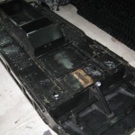
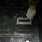

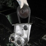

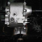

2. Lay the snowmobile frame on its side. Place one of the tracks in the niche of the snowmobile frame. Install the rear track shaft using 2 tensioners and 2 springs. Install the 2nd and 3rd roller carts. Please note that the left and right carts are different. When properly installed, the front wheel of the cart is at the outer edge of the track.
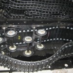
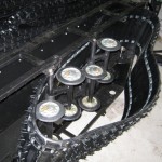

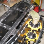

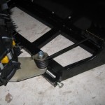

3. Install the rubber O-ring, circlip, bearings on the drive shaft. Install the track drive shaft through the track. Install the track drive shaft outer bearing housing, secure with 3 nuts.
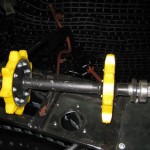
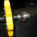

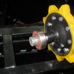

4. Install the track drive shaft through the track. Install the track drive shaft outer bearing housing, secure with 3 nuts.
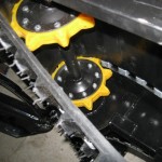
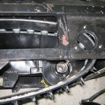

5. Flip the snowmobile frame onto its other side. Install the second track by repeating steps. 2-4.
6. Tension the tracks with the track tensioner bolts. Pay attention to even track tension. Do not overtighten the tracks as this will create increased resistance to movement of the snowmobile and lead to increased wear on the snowmobile mechanisms. Tighten the rear axle nuts.
7. Assemble the ski with leaf spring and king pin.
8. Install the ski assembly onto the snowmobile frame by threading the king pin through the tube on the snowmobile frame. Put the spring and the king pin lever on the splined shank of the king pin. Pay attention to the parallelism of the king pin arm and the ski axis.Tighten the spline with the bolt.
9. Place the snowmobile frame horizontally on the tracks.
10. Install the steering wheel support frame by screwing 2 M8 bolts to the snowmobile frame brackets. Install the brake bracket onto the 2 reversing box studs. Install the handlebar assembly with bushings and hub caps on 4 bolts, securing it to the steering wheel support frame at the top and to the brake bracket at the bottom. Screw the steering roller to the steering arm with an M10 socket head bolt. Secure the bolt with an M10 nut.
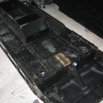
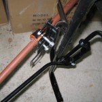

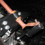

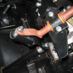

11. Install on the shaft of the reverse box in sequence the key, then the coupling half, the spring, the half-coupling liners, the movable disk, inserting the free end of the spring into the hole of the movable disk, then the spacer sleeve, the circlip, the key, the stationary disk. Secure the assembly with an M12 bolt, washer and lock washer.
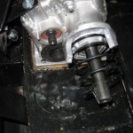
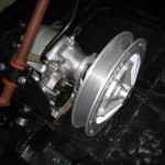

12. Install the reverse box control mechanism by attaching a lever with a square hole to the axle on the reverse box and fixing it with an M8 nut. Attach the bracket with the control handle with 2 M6 bolts to the steering shaft support frame.
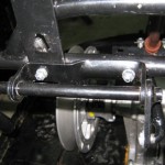
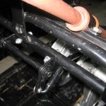

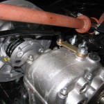

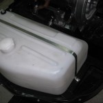
13. Install the fuel tank to the snowmobile frame. Secure it with a clamp by screwing the ends of the clamp to the studs on the snowmobile frame with M8 nuts and washers.
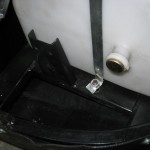

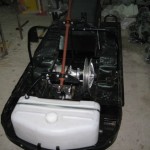

14. Install the 6x6 mm key, the brake disc bushing and the brake disc onto the intermediate shaft end of the reverse box. Fix the parts with the M8 shaped bolt and washer. Install the brake mechanism to the brake bracket using 2 M6 bolts. Install the brake control lever on the steering wheel. Connect the brake mechanism to the brake lever with a brake cable. Adjust the lever free play with the threaded sleeve on the brake cable.
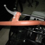
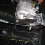

15. Install the seat onto the snowmobile frame. To do this, drill holes in the snowmobile frame for attaching the folding seat hinges. Attach them to the frame of the snowmobile using screws or rivets. Install the latch on the opposite side of the seat onto the snowmobile frame by drilling holes in the snowmobile frame to secure it.
The undercarriage of the snowmobile consists of a caterpillar propeller and a pivoting ski.
The crawler unit includes tracks, drive and guide shafts with sprockets, and roller balancers.
The tracks should be installed so that the right angle of the lugs on the lower branch of the tracks is facing forward, since the tracks crush the snow under them, and do not grab it.
Steel brackets installed between the windows are designed to accurately mesh the teeth of the drive and guide sprockets. Riding with dropped or damaged braces can lead to intense wear of the sprocket teeth and rapid damage to the tracks due to abrasion and rupture of the bridges between the windows.
Rice. 7 - the Driving shaft of caterpillars
1 - bearing housing; 2 - outer hub; 3 - an asterisk; 4 - inner hub; 5 - shaft; 6 - bolt; 7 - nut; 8 - bushing; 9 - cuff; 10 - bearing; 11 - washer; 12 - driven sprocket of a chain transmission; 13 - retaining ring
The drive shaft (Fig. 7) is located in the front of the snowmobile frame and consists of a steel hollow shaft 5 with hubs 4 welded to it, hubs 2 and sprockets 3 installed between them, each of which is attached to the hubs with bolts and self-locking nuts. At the ends of the shaft there are bearings 10 and rubber cuffs 9. Between the bearing and the cuff there is a locking
ring 13. The drive shaft is installed at one end into the bearing housing, welded to the crankcase of the reverse box, and by means of a slot at the end of the shaft is connected to the driven sprocket 12 of the chain drive, the other into the bearing housing 1 on the snowmobile frame. Washer 11 is installed between the driven sprocket 12 and bearing 10.
The guide shaft (Fig. 8) consists of a hollow shaft 23 with hubs 22 welded to it, hubs 17 installed between the hubs of sprockets 19, rubber seals 15 and bearings 14. A circlip 12 and a washer 11 are installed between the collar and the bearing.Lubrication of the bearings is carried out during assembly and during maintenance during operation through the hole in the cheek of the balancer, closed with a plug 13.
The guide shaft is installed in the aft part of the snowmobile frame on balancers 24. The spring 4 mounted on the balancer bushing is an elastic element of the guide shaft suspension. The short end of the spring rests against the bent hook of the balance bar cheeks, and the long one is inserted into the middle slot of the three-position comb 3. On the balance bar axis there are installed: spacer sleeve 8, washer 9, balance bar with a spring and a washer 7. On the balance bar axis there is a through threaded hole for an adjusting bolt 1 track tension.
The caterpillar is tensioned by a screw tensioning mechanism by moving the axes of the balancers in the longitudinal slots of the brackets welded to the sides of the frame and the middle rib. After adjusting the tension, the balance axles are fixed in the required position with self-locking nuts 5.
The roller balancers mitigate the shock and shock of the snowmobile. Each balancer consists of two pipe-welded balancer arms with rollers, two springs and an axle. The balancer axle is bolted to the frame brackets.
The elastic elements of the roller balancers are coil torsion springs. The track roller rotates on a bearing. The bearings are lubricated with grease introduced during assembly, and then during maintenance during operation through a hole in the outer cheek of the roller, closed with a plug.
Rice. 8 - Guide shaft with track tensioning mechanism
1 - track tension bolt; 2 - washer; 3 - comb; 4 - spring; 5 - self-locking nut; 6 - balancer axis; 7 - disc washer; 8 - spacer sleeve; 9 - washer; 10 - retaining ring; 11 - washer; 12 - retaining ring; 13 - plug; 14 - ball bearing; 15 - cuff; 16 - washer; 17 - outer hub; 18 - bushing; 19 - an asterisk; 20 - self-locking nut; 21 - bolt; 22 - inner hub; 23 - shaft; 24 - balancer
Ski and ski suspension. The steering ski (Fig. 9, 9a) is steel, stamped. At the bottom of the ski there is a runner 16, which protects it from abrasive wear.
The connection of the ski with the pivot is carried out through the leaf spring 2, which softens the shocks and shocks from the unevenness of the track. The spring deflection is limited by a rubber stop 17. The spring sheets are tightened with an eye by two clamps and self-locking nuts.
The spring assembly is attached to the brackets of the ski sole with the ends of the root sheet using 20 axles, locked with cotter pins. The longitudinal movement of the spring occurs due to the sliding on the bronze insert 18 of the front end of the root sheet.
The spring eyelet is attached to the ski pivot with a bolt 2 and a self-locking nut 23. The angular movement of the ski in the vertical plane is limited by a rubber buffer 3.
Steering. The steering control (fig. 9) consists of a rudder column, a rudder, a swing arm, a king pin and a shock absorber.
The rudder column is attached through bushings 10, which play the role of sliding bearings, to the brackets of the steering rack and the reverse box by clamping covers 13. The rudder 15 is connected by a cover and bolts to the rudder column housing.
Rubber buffer 3 is designed to prevent the ski from getting buried in the snow when the snowmobile is moving backward. The angle of rotation of the ski from the middle position is limited by a plastic stop 8 installed in the guide of the swing arm. Spring 6 is designed to eliminate gaps in the steering when the snowmobile is moving.
The steering column bearings, kingpin and swing arm guide are lubricated with grease.
Rice. 9 - Steering
1 - ski; 2 - spring assembly; 3 - buffer; 4 - kingpin; 5 - kingpin column; 6 - spring; 7 - lever; 8 - emphasis; 9 - roller; 10 - bushing; 11 - steering rack; 12 - steering column; 13 - top cover; 14 - cover; 15 - steering wheel; 16 - runner; 17 - rubber stop; 18 - insert; 19 - bracket; 20 - axis; 21 - clamp;
Rybinsk online snowmobile store.You can buy a snowmobile online, spare parts for Buran, Taiga snowmobiles.
Self-diagnosis of malfunctions of the Buran snowmobile.
At the initial stage, you need to familiarize yourself with the technical instructions from the snowmobile manufacturer, drawn up according to your vehicle model. Next, we will analyze the most common malfunctions of the Buran snowmobile.
Snowmobiles made in Russia do not suffer from frequent breakdown of electronics, but nevertheless, if this happens, then it can be diagnosed by sudden interruptions in engine operation. "Buran" begins to stall, most often there is no spark - this indicates that a coil or commutator needs to be replaced.
There are no problems with spare parts for Buran snowmobiles in Russia and they are quite cheap compared to their foreign counterparts. The replacement itself is quite simple, and it is quite possible even in the field, if you have a repair kit for the ignition system with you.
Malfunctions in the fuel supply system.
In domestic snowmobiles, interruptions in the operation of the fuel system sometimes occur. The main symptom of a breakdown is the interception of gasoline at high speeds, after which the snowmobile stalls.
When starting a cold engine, fuel system malfunctions are most noticeable. If you notice a malfunction, you need to sort out and thoroughly clean the fuel pump, or replace it.
It is also worth paying attention to the correct placement of the diaphragm. Repairing the fuel system in the field is not entirely comfortable, but possible. Therefore, it is advisable to have a complete fuel pump with you.
Defective gear and motor.
These breakdowns are quite rare on domestic snowmobiles and most often arise as a result of depreciation wear.
Symptoms, engine and gearbox malfunctions:
- Problems in starting the engine.
- Increased vibration, knocking in the engine and gearbox.
- The snowmobile is jerky.
- Power drop at high engine speeds.
- Increased fuel consumption.
- Fast heating of the engine.
- Oil or fuel leakage.
Engine repair requires certain knowledge, skill and special tools. If you have all this, then you can easily troubleshoot. Otherwise, you should contact the service center, where the malfunctions will be eliminated in the shortest possible time.
In any case, if you notice one or more of the symptoms of engine breakdown in your snowmobile, do not neglect and drive into the field or forest on it. A broken engine in the field can be a lot of trouble. Therefore, we strongly recommend eliminating all engine imperfections before long journeys.
Here you can find, buy spare parts for the Buran snowmobile at attractive prices and order the delivery of spare parts to any point in the Russian Federation.
The RMZ-640 "Buran" engine produced by the Rybinsk Motor-Building Plant is widely used not only on the snowmobiles of the same name, but also on deltalets. However, if individual snowmobile owners are satisfied with its characteristics to some extent, then pilots - with rare exceptions. And many of those who deal with RMZ for a long time are aware of the constant threat of cylinder overheating and piston burnout. Therefore, delta pilots are trying to replace the "six hundred and forty" engine with a better one, if possible with an imported one, or, at worst, improve it.
In general, they have few ways of improvement: either to improve the existing structure in detail, or to remodel it on a large scale. The most decisive go for a deep modernization, affecting the main systems of the Rybinsk motor. Regular readers of our magazine know examples of such modernization. The most famous, dating back to the fall of 1996, is given in the publications "Beetle-42: Transport for Heaven and Earth" (Modelist-Constructor No. 8,9,11 ’96).Anatoly Zhukov, the designer of the Zhuk deltaplane, increased the power of the 600th by equipping its cylinders with individual carburetors and mufflers. He solved the temperature problem radically by converting the engine from air to liquid cooling.
However, the reserves of the standard RMZ-640 are far from being exhausted. Many designers are engaged in the opening of these reserves: in Rybinsk, in the factory design bureau, and in other cities, in flying clubs, various laboratories and scientific and technical centers. Valery NOVOSELTSEV, an employee of the Moscow Scientific and Technical Center “Istok”, presents his version of improving the performance of the famous engine.
The article describes the work on the modernization of the RMZ-640 "Buran". The participants set themselves the task of improving the performance of a widely used engine. One of the main activities to accomplish this task was to refine the design of plate check valves.
In our case, we used a serial engine with serial number 88410219, which had previously worked on a two-seat deltaplane for 46 hours. The declared power of this engine is 28 hp. at 5500 rpm. It is equipped with a V-belt reducer with a gear ratio of 1: 2.15, a propeller with a diameter of 1.6 m and a pitch of 0.79 m, as well as standard A17DV candles and a K-62Zh carburetor with a diffuser diameter of 32 mm and a main jet with a diameter of 1.36 mm.
The engine ran on fuel consisting of a mixture of AI-93 gasoline (specific gravity 0.74) and MGD-14M oil in a ratio of 1:30. Fuel was supplied by gravity from a supply tank installed at a height of 2.5 m relative to the carburetor.
Before the tests, the valve timing was checked, the effective compression ratio was refined - it was Eef = 5.6. A low value of the average effective pressure of the serial engine was noted - only 3.56 kg / cm2.
All operations related to the removal of characteristics were carried out on a complex engine test bench made in the aviation department of the Scientific and Technical Center "Istok" and which made it possible to simultaneously register the values of torque, fuel consumption, speed and temperature of the cylinder heads.
The stand includes a balancing machine, a moulinette (wooden propeller with a diameter of 840 mm), a fuel flow meter (shtihprober) with hermetically sealed contacts (reed switches), a thermocouple with a dial indicator, and a fuel tank with a capacity of 10 liters.
To change the moment of resistance, six pairs of replaceable brake plates were attached to the ends of the moulinette blades, which made it possible to obtain seven points for measuring the parameters of the external characteristic.
The measuring base of the gauge consisted of three volumes controlled by reed switches, a magnetic float and three-way valves. Electronic tachometer - contactless, with an induction sensor. Temperature meter - aviation, registering the temperature of the cylinder heads under the spark plug.
To reduce frictional forces, all movable joints of the machine are equipped with rolling bearings.
The work was carried out in four stages:
1) taking the initial (control) characteristics of the serial engine;
3) taking the characteristics of the upgraded engine and checking it over on a hang-glider;
4) taking the characteristics of the upgraded engine without a blower and gearbox.
The first stage was carried out on a complex motor test bench.
Rice. 1. Units and parts of the serial engine RMZ-640 "Buran", which were re-manufactured or modernized.
Rice. 2. Modified inlet (a) and outlet (b) cylinder windows (the cylinder surface is deployed in the plane of the drawing).
Rice. 3. Modified piston (the surface of the piston is deployed in the plane of the drawing).
Rice. 4. Displacers in the crankcase:
1 - crank chamber; 2 - displacers (AMg-6); 3 - screw M4 (20 pcs.).
Rice. 5. Displacers on the crankshaft:
1 - crankshaft; 2 - displacers (glass fiber on epoxy binder); 3 - holes (drilling d4 to a depth of 0.5 mm, 20 pcs.).
Rice. 6. Block of cuffs:
1 - clip (anodized D16T); 2 - sealing ring, rubber (from VAZ-2108); 3 - cuff (from VAZ-2101, cut off).
Rice. 7. Valve box:
1 - plate valve (2 pcs.); 2 - box body (AL1); 3 - cover (AL1); 4 - screw M5 (8 pcs.).
Test conditions: outside air temperature + 2 ° С; atmospheric pressure - 746 mm Hg; fuel - a mixture of AI-93 gasoline with MGD-14M oil (1:30); carburetor - К-62Ж (main jet diameter - 1.36 mm; effective compression ratio Eef = 5.6); candles - А17ДВ.
The following results were obtained.
Propeller characteristic (external load - propeller with a diameter
1.6 m at 0.79 m steps): Ne = 25.8 HP at 5086 rpm, Ce = 0.433 kg / h HP
External characteristic (external load - moulinette): Ne = 27.9 HP at 5514 rpm, Ce = 0.416 kg / h HP Head temperature t ° C = 212 ° C.
The second stage is the actual modernization. Have undergone revision; crankcase (displacers are installed in the corners of the crank chamber), cylinder heads (the bearing surfaces of the heads are cut by
1.8 mm to increase the effective compression ratio, Eef increased to 7.2, the cylinders themselves (the intake and exhaust ports are bored), the crankshaft (displacers are installed in the cheek grooves), the cuffs of the crankshaft main journals (cut by 1 mm). The carburetor diffuser was also bored to a diameter of 33.6 mm, the diameter of the main jet was increased to 2.12 mm, and the height of the nozzle was reduced by 0.76 mm.
The valve timing (intake and exhaust) is increased. Each cylinder has two additional bypass channels with phases equal to the phases of the main channels (the cylinder liner was not pressed out in this case).
Made anew; pistons, valve box, box cover, plate check valves (plates, seats and stops), cuff clips.
The pistons are forged from AK12D alloy. They have two purge ports each, which lowered the temperature of the upper rings and piston heads and excluded burnout.
Unlike the serial piston, the skirt of the new piston is barrel-shaped and elliptical in accordance with the temperature gradient. The geometry of the skirt was adjusted experimentally. Since this process is rather complicated, it is possible to leave the standard pistons as well, modifying them according to the attached drawings.
The body and cover of the box of plate check valves are cast from АЛ1. However, it is possible to use any other cast heat-treatable aluminum alloy.
The valve seats are made by pressing from organite (or Kevlar, as this SVM is also called - ultra-high-strength material) on an epoxy binder heated to 80-85 ° C during the polymerization process. Saddle sizes with minor changes are taken from the book by V.M. Kondrashev and others (see Literature). The material of the valve plates is STEF-1 fiberglass, the stoppers are steel.
Since the placement of the valves and the bore of the cylinder windows increase the volume of the crankcase by 41 cm3 (which leads to a decrease in the purge pressure and, as a result, to a decrease in the maximum engine power), so-called displacers are installed in the grooves of the crankshaft cheeks and in the corners of the crankcase harmful volume. On the crankshaft, they are made of glass thread on an epoxy binder (for better adhesion of the winding to the cheeks with a drill with a diameter of 4 mm, holes with a depth of 0.5 mm are marked in them). In the crankcase, the displacers are aluminum half-rings of triangular cross-section, fastened with M4 screws.
The sum of the displaced volume in the chamber together with the volume displaced by the cuff yoke is 79 cm3, which more than compensates for the increase in volume from valve placement and window boring, which ultimately improves blowdown.
However, the increase in pressure in the crankcase led to the fact that the standard cuffs began to be squeezed out of the clips. This was revealed during the first engine starts. I had to make new clips and install in them cuffs from the semi-axles of the VAZ-2101 car, cut by 1 mm and facing each other with the front side. To seal the clips, rubber rings from the ignition shaft from the engine of a VAZ-2108 car were used.
Rice. 8. Plate valve:
1 - valve seat (organotili kevlar); 2 - M3 bolt (4 pcs.); 3 stopper (steel, 2 pcs.); 4 valve plate (fiberglass STEF-1, 2 pcs.).
Before mounting the cuffs, the clips were heated to 200-250 ° C. Then, TsIATIM-201 grease with molybdenum disulfite was stuffed in the cuff cavity, after which the clips were mounted on the crankshaft. Their shoulders are tucked into the crankcase recesses, and the standard thrust rings are dismantled.
In addition to these works, the usual two-stroke ICE procedures were carried out to refine the inner surfaces, that is, cleaning the casting in channels and windows and adjusting the mating lines of the crankcase and cylinders. More about this in the book of IM Grigoriev (see Literature).
Stage three. During repeated tests, the parameters of the external, screw, flow characteristics and the maximum temperature of the cylinder head under the spark plug were measured. The temperature and composition of the exhaust gases were not indicated. The power was brought back to normal conditions. The ignition system has not been changed or adjusted.
Test conditions: outside air temperature - 8 ° С; atmospheric pressure - 748 mm Hg; fuel and external load are the same as before the upgrade; the carburetor diffuser is bored to a diameter of 33.6 mm; main jet - up to a diameter of 2.12 mm; Eef = 7.2.
Results of tests of the upgraded engine.
Propeller characteristic: Ne = 31.7 h.p. at 5316 rpm, Ce = 0.321 kg / h HP; head temperature t ° Cmax = 204 ° C; increase in capacity - 22.8 percent, efficiency - 25.8 percent.
External characteristic: Ne = 38.2 hp at 5778 rpm, Ce = 0.332 kg / h HP Head temperature - t ° Сmax = 208 ° С; increase in capacity - 36.9 percent, efficiency - 20.25 percent.
And finally, the fourth stage. In the configuration without a gearbox and a blower, the engine spun up to 6840 rpm, the recorded power was 19.6 hp, Ce = 42.2 hp. at 5978 rpm, Ce = 0.338 kg / h HP
For the characteristics of the modernized engine, a new propeller with a Wortman profile RH-63-137 with a diameter of 1.6 m and a pitch of 0.8 m was designed and manufactured for a flight speed of 72 km / h. With him on the mooring lines, a thrust of 152 kg was obtained. Prior to this, the thrust on the mooring serial engine with a standard propeller reached 112 kg, after modernization - 135 kg.
The rate of climb of a two-seater hang-glider with a serial engine and a standard propeller was 1 m / s. After modernization, with the same propeller, - 2.5-2.8 m / s; and with the newly manufactured - 3-3.2 m / s, while the hourly fuel consumption did not exceed 9 liters.
The temperature of the head of the "hot" cylinder of the modernized engine during take-off and climb operation at an outside air temperature of + 28 ° C did not exceed 195 ° C.
Bottom line: after completing the listed stages of modernization, the engine's operation became smoother and smoother, starting was much easier. Almost all of its main characteristics have improved: power, efficiency, continuity and, most importantly, reliability. At the end of September 1999, the engine worked 32 hours in deltaplane flights without any remarks.
V. NOVOSELTSEV
1. Kondrashev V.M., Grigoriev Yu.S., Tupov V.V., Sillat P.P., Abramov V.I., Strokin A.N. Two-stroke carburetor internal combustion engines. - M., mechanical engineering, 1990.
| Video (click to play). |
2. Grigoriev I.M. A motorcycle without secrets. - M., DOSAAF, 1973.


