Details: TV samsung le32c350d1w DIY repair from a real master for the site my.housecope.com.
Material is added to the pages as data accumulates from the available technical documentation, personal author's experience and from the masters of repair forums. More details.
Technical description and composition of the SAMSUNG LE32C350D1 TV, panel type and modules used. The composition of the modules.
Inverter (backlight): I32HD_AHS BN44-00369B Rev-1.2
PWM Inverter: LX6523AID (14), LM358F (8)
Power Supply (PSU): BN44-00369B Rev-1.2 - I32HD_AHS
MOSFET Power: 13NM60, MDD3752 (3)
IC MainBoard: 1117Z, M167 950T45,
SAMSUNG
Model: LE32C350D1 LE32C350D1W
Inverter (backlight): BN44-00369B
PWM Inverter: LX6523AID, LM358F
Trans Inverter: 3324340046EF
Power Supply (PSU): BN44-00369B
MainBoard: BN41-01537A (BN94-02670Q)
IC MainBoard: K4T1G1640FR-BCF8, Z1031A1, BAOH55, ATMLH016, NTP7300S, DRU603, WT61P802, ATMLH032, ATMLH014
Tuner: DT0S40FVL082A BN40-00197A tuner BN40-00202A
Control: BN59-01005A, IR: BN41-01411A BN96-13063B
LE32C350 Specifications
Repair SAMSUNG LE32C350D1 must begin with the diagnosis of the malfunction and a careful examination of its external and internal elements, including body parts. Often, according to certain external signs, it is possible to draw some conclusions about the reasons for the failure of certain elements of the circuit even before taking the necessary measurements, which will make it possible to determine a further algorithm for troubleshooting and localizing a defect. Experienced repairmen often guess about the causes of the defect and the possible consequences, for example, by ring cracks in the soldering of the element terminals, as well as by swollen capacitors or resistors burned out to coal dust and other external indirect signs.
| Video (click to play). |
In cases where the SAMSUNG LE32C350D1 TV does not turn on, does not respond to the remote control and buttons, no indicators on the front panel light up or blink, and there are no sounds and no signs of operation at all, - the BN44-00369B power supply module is most likely faulty, or, which happens much less often - there is no power for the processor on the motherboard. Diagnostics of the power supply should always begin with checking the fuse and, if it is broken, it is necessary first of all to check the diodes of the rectifier bridge and the power switch for the likelihood of an avalanche or thermal breakdown.
If a breakdown of the power switch of the flyback converter of the power supply is detected, it should be remembered that it does not fail without reasons that should be looked for by checking other elements of the primary circuit - electrolytic capacitors, PWM controller ICE3BR0665JZ, LX6523AID, LM358F, which can only be checked by replacing , as well as other semiconductor elements (diodes, transistors, zener diodes).
If an active PFC (power factor monitoring) circuit is used in the power module, troubleshooting becomes somewhat more difficult.
The TV model LE32C350D1 uses a power module BN44-00369B, combined with an inverter (a converter for powering backlight lamps). In the latest models of LCD and LED TVs, this circuitry is widely used and does not complicate the search for defects during module repair at the component level.
If, when turning on the TV, the image appears and immediately disappears, or is absent initially when turned on, but there is sound and other functions work, there is a high probability of a malfunction of the inverter (backlight power converter). In such cases, the lamps, the inverter and the common power module must be checked, in which the electrolytic capacitors of the rectifier filter supplying the inverter must be checked.
Repair of the BN44-00369B inverter can often be somewhat complicated by the device of special protection circuits, which are designed to turn it off in emergency situations for fire safety purposes when lamps are depressurized, or short circuits or breaks in high-voltage circuits and connections. Sometimes it becomes necessary for diagnostics to block the protection circuits in order to be able to make the necessary measurements at the control points of the circuit.
In such cases, special care should be taken when diagnosing, and after all repair work is completed, it is imperative to restore the circuits and the operation of the inverter protection for the further safe operation of the TV.
When trying to repair the motherboard, you should first check the serviceability of linear stabilizers or microcircuit power converters and, if necessary, update the software (software). If it is not possible to replace the MB (SSB) board, it is necessary to check the serviceability of its elements - K4T1G1640FR-BCF8, Z1031A1, BAOH55, ATMLH016, NTP7300S, DRU603, WT61P802, ATMLH032, ATMLH014. Defective components must be replaced.
We remind users again! Attempts to self-repair the SAMSUNG LE32C350D1 TV without the appropriate qualifications and experience can lead to its complete non-repairability!
Download : Service Manual and Diagram Samsung LE26C35 ***, LE32C35 *** Chassis N82B.
The appearance of the MainBoard BN41-01537A is shown in the figure below:
On tv LE32C350D1 power module installed BN44-00369B using a PFC (Power Factor Correction) circuit that performs the function of an active filter to eliminate the higher harmonic components of the consumed current. A boost converter based on a PWM regulator FAN7530 does not allow connecting the electrolytic capacitor of the input rectifier filter to the network directly through open diodes, when the charge current is determined by its reactance (about 15-30 ohms at a frequency of 50 Hz). As a result of the conversion, the charging current of the capacitor will be determined in such a way that the envelope of the high-frequency pulses of the input current follows the phase and shape of the sinusoid of the input voltage. Checking the health of the PFC unit is carried out by measuring the DC voltage across the capacitor of the mains rectifier. In working mode, it should be about 380V, in standby about 300V.
External view of the power supply
The main features of the device SAMSUNG LE32C350D1:
Installed matrix (LCD panel) T315HA01-DB.
Matrix control uses Timing Controller (T-CON) V315B5-XC06.
To power the backlight lamps, the BN44-00369B inverter is used, controlled by the LX6523AID, LM358F PWM controller. The transformer 3324340046EF is installed in the inverter converter.
The formation of the necessary supply voltages for all nodes of the SAMSUNG LE32C350D1 TV is carried out by the BN44-00369B power module, or its analogs using the LX6523A, FAN7530 (PFC), ICE3BR0665JZ (Standby) microcircuits.
MainBoard - the main board (motherboard) is a BN41-01537A module, using K4T1G1640FR-BCF8, Z1031A1, BAOH55, ATMLH016, NTP7300S, DRU603, WT61P802, ATMLH032, ATMLH014 and others.
Tuner DT0S40FVL082A BN40-00197A tuner BN40-00202A provides reception of television programs and tuning to channels.
SAMSUNG LE32C350D1W Chassis N82B Model Code: LE32C350D1WXRU
Panel type (matrix): T315HA01-DB,
Motherboard: BN94-02670C, Tuner: BN40 - 00173A,
PSU: BN44 - 00369B
Information about the composition of televisions on this site is accumulated from the records of repairmen and forum participants.
Be careful! Typos and errors possible!
My knowledge in the repair of this type of equipment: There is little experience in renovation
Scheme availability: Already there - downloaded thanks to https://my.housecope.com/wp-content/uploads/ext/2561/forum/46-23854-230527-16-1352197007
SAMSUNG Brand
Model LE32C350D1W
LE32C350D1WXUA code
Type LE32C350
Lane's composition:
Prots - unknown, the radiator is glued.
IC 1201
- Decal 1107-001940 2003.1 AUTO PRO (B)
- under the sticker SEC 028 HIB6 KFG1616U2D FKF056 AC
IC501 - ATMEL H022 2ECL13 (24C256)
IC502 - ATMEL 951 02B 1 (24C02)
IC1071 - S24SC02AVK6 (24C02)
IC901 - ATMEL H016 02B 1 (24C02)
IC903 - KIA7805AF
IC202 - 78M09A
IC208 - 1117 Z
IC207 -M163 950T45
IC204 - Z1031A1
IC203 - Z1031A1
IC706_EU - DRV603 04TG4
Tuner - DT0940FVL082A BN40-00197A
_______ Related Links -__________________________________________
https://my.housecope.com/wp-content/uploads/ext/2255/forum. start = 0
https://my.housecope.com/wp-content/uploads/ext/2561/forum/61-23784-1 - The chassis is indicated here, but I'm not sure if the information is correct
https://my.housecope.com/wp-content/uploads/ext/2255/forum. 3245163
https://my.housecope.com/wp-content/uploads/ext/2561/board/lcd_pdp_tv/samsung/le32c350/241-1-0-5372 - sewed with this firmware (maybe not suitable?)
Servicemanual - https://my.housecope.com/wp-content/uploads/ext/2561/forum/46-23854-230527-16-1352197007 on the link from this post and in the search le32c350 (direct link does not come out)
_____________________________________________________________
First of all, I checked the weekend with the PSU - the norm is 12.9 and 5.06 volts.
Then the backlight inverter came under suspicion - the call of the broken parts did not reveal it. I dismantled the trans backlight inverter - checking with a generator with a swing for the primary from 15 volts of change - at the output there is a pure sine. Vitkovy did not notice. I did not drive at full without load from the generator, I am afraid of a breakdown.
I can’t check the matrix illumination (by current and voltage) yet - the Gnerator device is 98% assembled and has not yet been launched and debugged. literally a few days and I think I will finish the device.
Since the backlight and power supply unit were not noticed, the defect was passed on to checking the lane.The voltage map on the stabilizers was removed - I attach it in the files.
Again, I don't see any obvious crime - we can and what I missed.
I moved on to checking the version of the firmware rally - the IC501 was overwritten with the firmware downloaded from the monitor, and then from this (repair-aud.no) site - it did not help. The symptoms are the same. Blinks with a light and sometimes a matrix backlight.
The firmware also contained a flash file - but the flash was not found on the board - according to fragmentary information, the flash is in the process or subprocess? How to merge the firmware from there and write it down until I understood.
When you try to turn it on, voltages appear on the stabilizers of the lane, but disappear when the TV does not turn on.
Also, in time, signals appear and disappear on the connector from the power supply unit to the lane. +13 and +5 do not disappear. Yes, in the power supply unit, the prekonday works on the network bank about +400 volts.
You can download the file after registration registration | entrance
Modest Ichthyophile
Posts: 5955
my.housecope.com/wp-content/uploads/ext/2255
Posts: 10110
Varnava wrote:
On the network bank 390 V
Monitoring during the entire cycle revealed a drawdown of up to 310 V. After replacing two electrolytes, CP805 and CP802, there was no drawdown. But nothing has changed in the operation of the TV.
When installing a clean eeprom, the TV turned on in standby mode. When you turn it on from the remote control, the LED blinked off, but the screen did not light up. The TV received commands from the remote control, but there was nothing on the screen. After unplugging and plugging it back in, everything started all over again.
my.housecope.com/wp-content/uploads/ext/2255
Posts: 10110
Modest Ichthyophile
Posts: 5955
my.housecope.com/wp-content/uploads/ext/2255
Posts: 7096
valya wrote:
Well, so maybe it's all about precondition?
Connect through the lateral, you will immediately see
It seems not in it. With the lane turned off, I loaded the unit with 5 V 4.7 ohms. And set the rheostat to 13 V and increased the load to bring the voltage to 12.6 V. At the same time, 393 Volts are rooted to the spot. And the lamps glow at full intensity. and there are no ripples.
The voltage drop when the mains are connected occurs gradually, after turning on the inverter and supplying 13 V to the matrix, from 393 to 350 volts, after which a reset occurs and the voltage rises sharply to 393 V with a short pulse up to 400 V.
In this manual, we will consider the process of repairing an LCD TV from Samsung, model LE32R81B. The stated problem is no image.
The TV is connected to the network. The operating mode indicator in the lower right corner flashes continuously.
When you press the power button on the remote control, the indicator responds, but the image does not appear. Also, when you press the buttons on the remote control, there are no sounds.
We remove the TV board and begin to figure out what the problem is.
The TV has a LE32R81BS / KLG board.
The alleged problem is a 512Kb eprom stick.
The fact is that the previous repair of this TV was also associated with the replacement of a missing 512 KB eprom flash drive. Only two months have passed since the purchase of the TV.
At the same time, all the supply voltages on the board were checked for ripple, the supply voltage on the flash drive itself, on the pull-up resistors, that is, the shape of the pulse on the clocks data pins on this microcircuit was looked at. No other problems were found.
After replacing the flash drive, the TV turned on normally. A little more than a year has passed since the previous renovation.
Let's try to replace this microcircuit again.
If the problem was in the electrical part, that is, ripples or abnormal voltages, then the TV simply would not work, or returned to repair much earlier.
The repair will consist of replacing the USB flash drive, checking the TV for inclusion and entering the service mode in order to transfer it to normal mode for using the TV.
We clean up the contact pad.
We solder a new clean USB flash drive.
Do not forget to clean the board from the flux residues.
Basically, you don't have to look for the firmware. We return the board to the TV, restore all connections and turn it on.
The picture appeared on the monitor.
Now we go to the service menu to prepare the TV for normal operation.Because if the TV remains in this mode, it will restart itself cyclically every 10-15 seconds.
We enter the service menu using the remote control. To do this, turn off the TV with the Power button. Then very quickly, within a second, press in turn the Info, Menu, Mute and Power buttons.
After entering the service menu, we will again have about 10 seconds to make all the necessary changes.
Navigation through the menu items is done with the cursor up / down buttons, the Enter button to enter the selected menu item, changing the values of the menu item with the left / right cursor buttons on the circular block of buttons.
We enter the second menu item Option Table (Service).
We select the Ready parameter and change the OFF value to ON.
To exit the service menu, it will be enough to press the Power button. The TV turns off, restarts with the changes made.
It is strongly discouraged to change any values in the service menu if you are not sure of 100% correctness, otherwise you may end up with a TV that is unusable for repair.
The TV is now ready for use. It remains only to enter the menu to configure the TV, because all the parameters are at factory defaults.
So what needs to be done?
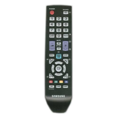
1. First of all, we enter the TV service menu - for this you need to sequentially press one after the other (and not simultaneously!)
TV buttons on the remote control [INFO] [MENU] [MUTE] [POWER] wait a couple of seconds and the TV turns on.
2. Press options and in the model item change "С350" to model "С450"
3. press control and in going to the hotel mode item change "off" to "on"
4. Go to the hotel mode menu and launch "Clone TV to USB"
5. Now go to the control menu and the Config Option item should appear there
6. then go to Config Option and in the Num of HeadPhone item change "1" to "0"
7. return to the control menu, the hotel mode item is returned to the value "off"
If this is not done, the channel manager will not work.
8. That's all, now we turn off and turn on your TV - and both video and sound should work!
The picture when viewed is amazing. Truly high definition TV.
If you didn’t succeed, then you probably do not have such a TV firmware and this is not possible. In this case, in the reverse order, return all the changes to what they were.
Such a problem, the tuner model was changed on the TV set in the service menu and after that it was not turned on. what do you advise. I am creating a topic for the first time, if something is wrong, do not judge strictly.
Change everything back, as it was and NEVER go there again.
In this case, install the native firmware where it was changed.
Are we going to repair it or let it work?
"A person cannot be helped against his will." G. Pomerants
This is understandable, but how to do it? He is not on (((If possible in details.
Connect the programmer to the MS and fill in the native firmware. How else is that?

Look for step-by-step instructions on the net, but there is a chance to completely finish off the TV, this is not a floor lamp.
Are we going to repair it or let it work?
"A person cannot be helped against his will." G. Pomerants
Yes, you are a direct captain of the obvious. If I had the opportunity, I would not ask questions. Are there any options like Hard reset or somehow revive and change the tuner model back.
Are there any options to somehow revive
How do you imagine it?

Do you have any reprogramming experience and the necessary equipment?
Are we going to repair it or let it work?
"A person cannot be helped against his will." G. Pomerants
on the TV set in the service menu the tuner model was changed and after that it was not turned on.
that is, by the combination [INFO] [MENU] [MUTE] [POWER] it is not included in the service?
No, not included. I found an option with short-circuiting the EEprom. What happens after the factory reset. (What settings need to be set there). And where is the factory reset in the menu.
tmn2009nick how did you solve this problem i have the same
tmn2009nick please, if possible, send an email solution to the problem in more detail
If it is not possible to reflash the memory yourself, then let the people who have studied this do it. For such a procedure, you need experience and some equipment. A non-knowledgeable person can wind snot on his fist like this and the master will not help. But if you have already decided to flatter in the menu service, then from each page, you need to write down all the settings data on paper, and only then proceed with the settings at your own peril and risk. And in no case should you touch RESET, otherwise there will be no way back.

MAN-sounds proudly, looks disgusting!
Samsung TVs are very common in our country: the Ukrainian buyer is attracted by the adequate price for the models and modern functionality. We, masters, love Samsung TVs for their ease of repair and maintenance. They have a simple design, many operations are predictable, and the manufacturer issues detailed technical documentation. Thanks to this, it is often possible to repair the TV at home.
But if the breakdown is serious and requires replacement of parts and full diagnostics, for this type of work it is worth giving the technician to the workshop so that the specialist can carry out repair work in the workshop.
What can break in LCD and LED TVs Samsung
There are several standard breakdowns typical for modern Samsung TV models. Here are some of them:
Software problems and more
Often you have to do Samsung TV repair in the software part: software failures can be identified by the disappearing settings of TV channels, the appearance of specific distortions when viewing in the "Cinema" mode, incorrect operation of the backlight. A software failure can also render the TV completely inoperable.
A separate topic is the malfunction of the LCD-matrices of Samsung TVs. Most often, it is expressed in the form of the appearance of vertical stripes on the entire screen or in certain parts of it. The reason for such a defect in most cases is a violation of contacts in the connections of the loops. This means that you need to disassemble the matrix and restore contacts - the work is difficult, and a good result is not always guaranteed.
Who should you entrust Samsung TV repairs to?
It is clear that every customer wants a quick and inexpensive repair. Professional and responsible TV repairmen can be found on the website of the Ukrainian service - it allows you to select performers with normal rates.
When placing an order, you can determine the necessary conditions and thus find a master who knows exactly how to service Samsung TVs. The listed malfunctions of TVs of a popular brand make it clear: the "home master" has nothing to do there. He will not cope with the repair and can only make it worse. Modern equipment should only be serviced by a qualified professional.
I could not find the firmware for the LA32C30D1 model anywhere, and in general, for some reason, it is not on any off site, except for stores. Because what and how to flash, I do not know.
While I was writing, I found the firmware for LE32C350D1W on the Ukrainian site.
Can I flash my TV with the firmware from the Ukrainian site?
After all, the difference in the second letter in the name is not critical. But what about the last letter W?
I don’t have enough experience in repairing TVs, but my mother has already scolded, with the words “fucking master, you can’t set up a simple TV”: rofl:
So, brothers, please help: unknw:
Friends, I figured out the question:
In the service menu, the demo mode was turned on. Namely:
Control - Hotel Option - on
It was necessary to turn it off.
The topic can be closed.
Recently, the TV in the kitchen Samsung CS-14F2R broke down quite unexpectedly. At first, this caused a feeling of similar joy - he had been behaving disgustingly for a long time and often there was a desire to throw him off the second floor, replacing him with a new one. However, the economic blockade and, as a result, inadequate prices for household appliances in our area, forced to take up the tools.
The very first examination after the autopsy showed that TDKS had burned down. Checking the line transistor D2499 revealed its breakdown in all directions.
Since transistors rarely go to this state on their own, it became obvious that there was some hidden reason that caused it to unacceptably open and fail completely. I had to turn to Internet services in search of a scheme. It turned out to be difficult to find TV circuits by name, as manufacturers based on the same typical scheme produce different models of devices with different CRT diagonal, and often there are clones from other manufacturers. Therefore, what they all have in common is not the diagram, but the chassis number.I found the inscription KS1A on the board. After downloading an archive with a similar chassis diagram and technical documentation for it, I began to study the diagram. Like any electronics repair, I decided to start with the power supply, or rather its launch. Having evaporated the TDKS and the line transistor, I thought about how to make the power supply work without the specified details. It is highly likely that without a load in the form of TDKS, it will not start. The diagram shows that the switching power supply generates two voltages: 13 and 125 volts.
Since 125 volts from the transformer of the switching power supply are fed to the TDKS, and 13 volts is involved in the control of the line transistor, he made the assumption that it was their increase that caused the failure of these parts.
Having sealed off the cathode of the diode D805 (it is he who serves to rectify 125 volts), he soldered a regular 100 W lamp to it. Thus, after switching on, the high-voltage part of the circuit will be de-energized, and it will be possible to check on the lamp what voltage the power supply is giving out.
Turning on showed that the power supply was started. However, instead of 125 volts, 150 volts are present! Instead of 13 - 15.5 volts. Checking the zener diodes in the PWM harness on the KA5Q0765 microcircuit did not reveal any crime. But the capacitor C802 for 33 microfarads of 50 volts due to its age (the TV is 13 years old) aroused suspicion. Since there was nothing besides a multimeter to check it, I decided to replace it. At hand was at 33 microfarads 63 volts.
After replacing it, the voltage at the output of the power supply dropped to 13 and 127 volts, which is absolutely acceptable. For reinsurance, I changed all electrolytes in the hot part - С812, С813, С815, С827, С304, С306.
Replaced the burnt out TDKS Samsung FSA 38032M with its Chinese-made 14A004C (S) analogue and a line transistor. To be on the safe side, due to the rather tough operating mode of the line transistor, I installed it on a radiator of a suitable size through thermal paste.
After turning on the device and making sure it worked, after an hour's run, he began to eliminate the old ailments.
This TV suffered from two more malfunctions:
- disgusting sound (the impression was that the vowels were falling out of the words)) and in order to hear something more or less good, it was necessary to increase the volume. It is difficult to say when such a malfunction occurred, but to remember whether it sounded good is even more difficult;
- the second malfunction was that the conceived switching of channels, even from the remote control, even though the buttons on the front panel, only led to the fact that only the channel number changed, and the image and sound remained the same.
I began to fight the first malfunction by connecting external acoustics from a computer - the sound turned out to be quite decent. Thus, everything turned out to be in order with the processor from which the sound signal comes out. And the reason should be sought in the ULF and standard dynamics. Replacing the dynamics did not give results. Therefore, it was worth paying close attention to the ULF, which in this TV is built on the TDA8943SF. It is worth noting that for different TV models on the KS1A chassis, ULFs are built on different microcircuits. The power supply of the microcircuit turned out to be normal - 12 volts.
In a typical switching circuit of this microcircuit, there is an electrolytic capacitor with a capacity of 10 microfarads 16 volts. Through it, the sixth terminal (reference voltage) of the TDA8943 is connected to ground. It was decided to replace it, which led to the restoration of normal TV sound.
The problem with switching channels had to be solved by resorting to the experience of other people who faced the same problem. Just like me, everyone noticed one oddity - if the channels were switched incorrectly, tugging on the antenna cable helped to restore the correct setting! As it turned out, there are many. And this malfunction occurs in Samsung TVs. The reason for this is the frankly poor soldering of the tuner, or rather the soldering points of the mass of the tuner board with its body and massive mass contacts on the board itself.
At first I wanted to completely solder the tuner, but I could not do it with a 25-watt soldering iron. I had to solder the tuner as it is, removing both of its covers.And although there is very little space on the chassis board for such maneuvers, we still managed to defeat this nuisance. Now the channels are switched without incidents.
Poor soldering needs to be said separately. A close inspection of the entire chassis board revealed many places where the soldering had to be repaired.
What became the reason is difficult to say - whether the soldering quality was initially poor, or the TV's long service life. But after the manipulations made, the TV again took its place in the kitchen.
Repairs were carried out by Nikolay Kondratyev, Donetsk.
They brought LCD TV SAMSUNG LE32B530P7W for repair with a malfunction: no signal or weak signal. Main BN41-01165B model: SATURN4_DTV_REV. Wiggling the tuner antenna jack will help a little. After a minute, the signal disappears or weakens again. We open the TV and take measurements of all voltages from the power supply unit and on the tuner
The voltages at the controlled points correspond to the nominal value. We remove the lane to solder the tuner.
As you can see, there are three microcircuits on the bottom of the tuner scarf. S5H1432A01-JO, TDA9898V3, TDA6651TTC3. The average TDA9898V3 gets very hot in operating mode. A microcircuit in an SMD case, we solder its conclusions with a needle tip of a soldering iron under a microscope with POS60 solder, and for reliability we also solder the second SMD microcircuit. A topic similar to this has been raised more than once on special forums, for example: https://my.housecope.com/wp-content/uploads/ext/2254/viewtopic.php?p=2071368 or - a solution to repair or replace the tuner.
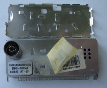
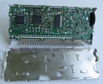

Under the microscope, it was very clearly seen that the soldering of the pins of this microcircuit simply fell off, so I had to solder with a needle with a needle well to fill the soldering place with flux for SMD components. 3 months warranty. Let's look at the time this soldering will last.
In this manual, we will consider the process of repairing an LCD TV from Samsung, model LE32R81B. The stated problem is no image.
The TV is connected to the network. The operating mode indicator in the lower right corner flashes continuously.
When you press the power button on the remote control, the indicator responds, but the image does not appear. Also, when you press the buttons on the remote control, there are no sounds.
We remove the TV board and begin to figure out what the problem is.
The TV has a LE32R81BS / KLG board.
The alleged problem is a 512Kb eprom stick.
The fact is that the previous repair of this TV was also associated with the replacement of a missing 512 KB eprom flash drive. Only two months have passed since the purchase of the TV.
At the same time, all the supply voltages on the board were checked for ripple, the supply voltage on the flash drive itself, on the pull-up resistors, that is, the shape of the pulse on the clocks data pins on this microcircuit was looked at. No other problems were found.
After replacing the flash drive, the TV turned on normally. A little more than a year has passed since the previous renovation.
Let's try to replace this microcircuit again.
If the problem was in the electrical part, that is, ripples or abnormal voltages, then the TV simply would not work, or returned to repair much earlier.
The repair will consist of replacing the USB flash drive, checking the TV for inclusion and entering the service mode in order to transfer it to normal mode for using the TV.
We clean up the contact pad.
We solder a new clean USB flash drive.
Do not forget to clean the board from the flux residues.
Basically, you don't have to look for the firmware. We return the board to the TV, restore all connections and turn it on.
The picture appeared on the monitor.
Now we go to the service menu to prepare the TV for normal operation. Because if the TV remains in this mode, it will restart itself cyclically every 10-15 seconds.
We enter the service menu using the remote control. To do this, turn off the TV with the Power button. Then very quickly, within a second, press in turn the Info, Menu, Mute and Power buttons.
After entering the service menu, we will again have about 10 seconds to make all the necessary changes.
Navigation through the menu items is done with the cursor up / down buttons, the Enter button to enter the selected menu item, changing the values of the menu item with the left / right cursor buttons on the circular block of buttons.
We enter the second menu item Option Table (Service).
We select the Ready parameter and change the OFF value to ON.
To exit the service menu, it will be enough to press the Power button. The TV turns off, restarts with the changes made.
It is strongly discouraged to change any values in the service menu if you are not sure of 100% correctness, otherwise you may end up with a TV that is unusable for repair.
The TV is now ready for use. It remains only to enter the menu to configure the TV, because all the parameters are at factory defaults.
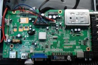
The motherboard in the TV performs a huge number of processes and can rightfully be called the main TV board, as well as the motherboard, SSB block or Main Board. It contains the control units for the entire television device as a whole and each of its parts separately. Repairing a motherboard at home is very laborious due to the complex diagnostics of this unit without the appropriate measuring and service equipment. The only way in this case is to use the best practices for typical defects on repair sites, including ours. A lot of materials of this kind have been published in the section "Malfunctions of TVs" and, judging by the comments to them, these materials have helped more than a dozen people with the repair of a TV at home with their own hands.
- 1 Performing operations at the command of the user from the remote control or local keyboard. Execution of commands to turn the device on and off, switch to standby mode
- 2 Adjusts the settings for the color reproduction of the image: brightness, contrast, saturation, etc.
- 3 Change the sound settings to create the most user-friendly sound experience
- 4 Automatic or manual search for analogue and digital TV channels from the built-in tuner
- 5 Fulfillment of individual user preferences and software update
- 6 Commutation of connected external inputs and peripheral devices
This is not the full range of responsibilities of the motherboard, but only a part of them. The development of television technologies, the introduction of Smart TV, multimedia and other innovations add all new components and nodes to the SSB board. Below is a block diagram of the main board of a Philips TV based on TPM4.1E LA chassis, released in series a few years ago:
The core of the motherboard is represented by the MT8222 central processor, which performs most of the functions assigned to this unit, together with storage and information exchange devices DDR, SPI Flash ROM, NVRAM. EDIDs are designed to match Plug and Play external devices to the TV chassis, allowing it to recognize and adapt to connected external equipment without user intervention or minimizing it. The tuner and sound channel are required for the main board, and the WT6703 STDBY MCU processor executes commands from the control panel and keyboard. The video signal, converted according to a certain algorithm, is fed through the LVDS bus to the matrix controller (Tcon), which is usually performed as a separate unit, and then to the LCD panel.
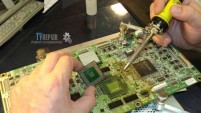
- 1 Malfunction of one of the secondary DC / DC converters located on the Main Board
- 2 Failure of software in the memory chips of the device Eeprom, SPI Flash, Nand
If in the first case, DIY SSB repair is still possible using original spare parts or universal converters, then not everyone can solve the issue with the firmware on their own without a programmer and software.
| Video (click to play). |
Do not forget to bookmark this page on your social networks!


