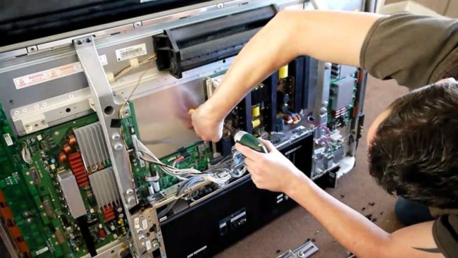
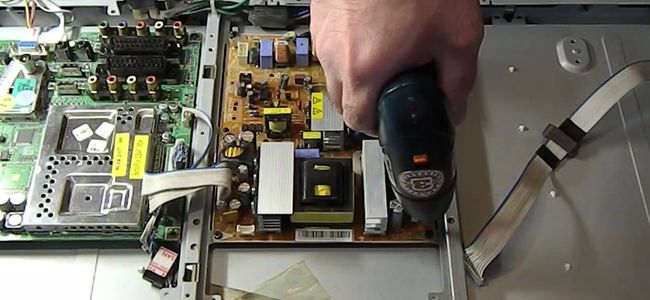
In detail: do-it-yourself samsung TV repair from a real master for the site my.housecope.com.
Samsung has long been one of the most popular brands sold and serviced in Russia.
The choice of buyers is justified by the favorable price-quality ratio of the equipment, and the popularity among repairmen is due to many factors that determine the simplicity and ease of repair and maintenance.
Despite the variety of models, Samsung TVs for technicians and service engineers remain uncomplicated and predictable in repair, and the manufacturer's timely technical support with components, modules, documentation and software greatly facilitates and simplifies diagnostics and repairs.
Since the beginning of the nineties of the last century, the craftsmen have accumulated rich experience in repairing Samsung TVs, which was discussed and preserved on the Internet in numerous conferences and blogs of repairmen.
Typical defects of some models sometimes caused controversy and deserve special attention in considering the causes of malfunctions and methods of their elimination.
In this series of articles, it is planned to consider the most common malfunctions of Samsung CRT TVs from 2000 and the most popular LCD TV models in the repair practice.
There is no need to consider the problem of electrolytic capacitors in the rectifier filters of power supply modules, since this is a massive trend characteristic of the first generation of LCD TVs. It should be noted that in LED TVs, the problem with electrolytic capacitors is less common. Perhaps this is due to the lower consumption of LED backlight power converters.
| Video (click to play). |
Operation of some first generation Samsung LCD TV models with defective power filter capacitors may cause software failure. At first, the settings for the channels may disappear, sometimes specific distortions appear in the “Cinema” mode, the screen backlight adjustment may not work correctly.
Often there is a complete failure in the software and the TV is no longer included in the operating mode.
In such cases, after repairing the power module, it is necessary to replace the contents of the EEPROM memory.
One of the most popular power supplies in repair is described separately in the article Typical faults BN44-00192A. In addition to defects caused by a malfunction of electrolytic capacitors, we note two more typical malfunctions of this module. Ring cracks in the soldering of the terminals of the switch-on transistor from standby mode, as well as breakdown of the sealant with subsequent short circuit and damage to the 2200pF capacitor and breakage of the 0.22 Ohm resistor in the power supply circuit of the key transistors of the converter.
Noise in the image in the form of curved oblique stripes associated with poor filtering of the tuner's power supply is eliminated by replacing the 100uF 16V capacitor on the main board. In this case, there is no need to change the capacitor in the tuner. Sometimes the masters do the opposite, due to insufficient competence, then such a replacement will help for a short while.
Another popular typical malfunction of some Samsung LCD models is the use of the AS-15 gamma correction chip in the T-CON board. AS19. The defect is associated with distortion of color transitions. The image becomes lighter and in places looks like a negative.
The latest LCD models, SMART-TV in particular, have problems with BGA soldering technology for highly integrated chips. In such cases, malfunctions may occur, usually manifested with warming up, which are caused by a violation of the contact of the chip pins with the corresponding pads on the board.
The malfunction of the LCD matrices is perhaps a separate topic for discussion, but it makes sense to briefly consider some of the external manifestations of its defects.
In most cases, these are straight vertical stripes in certain areas of the screen or throughout its entire area. Stripes can be different, both colored and black and white of different thickness.
Sometimes the nature of the stripes changes with external mechanical stress. Freeze-frame images may appear.
Such matrix defects are associated with broken contacts in the connections of the loops, which can sometimes be restored with warming up.
Repair of the matrix in such cases is associated with its disassembly and restoration of contacts in loops or duplication of connections with external conductors - a complicated process, not recommended by manufacturers and may not always be a successful and reliable solution to the problem.
Due to the fact that the price of the matrix is quite high, accounting for more than half of the cost of a TV, in most cases, owners of post-warranty TVs refuse to replace the matrix due to the economic inexpediency of repair.
In many models of LED TVs of the 5 series, panels (matrices) with backlight LEDs of sufficiently low quality are installed, or the current in the LEDs is incorrectly calculated. This currently popular typical defect can manifest itself already in the first year of operation. In this case, there is simply no picture.
In authorized service centers, on the recommendation of the manufacturer, they change the LED rulers and limit the current in the LED drivers so that the TVs work out at least the warranty period. And in post-warranty cases, this problem is solved by the craftsmen in different ways, depending on their qualifications and contractual conditions with the owner.
Some explanations and recommendations can be found in the article in our article Repair of Samsung, LG LED-backlights.
Of the most common malfunctions of Samsung CRT TVs, there are several associated with the low reliability of CRTs and their deflecting systems (OS).
The consequence of shorting the filament with the cathode of the kinescope (usually green) is eliminated by isolating the filament from the mass and organizing its separate power supply (2-3 turns per TDKS core). In this case, do not forget to use the standard filament current calibration resistor.
In kinescopes with a flat screen, diagonals of 20 inches or more, a short circuit between the accelerating electrode and the modulator (G2 and G1) often occurs, which is accompanied by the absence of an image.
Fortunately, such short-circuits, in most cases, can be easily eliminated by the usual old-fashioned methods popular among repairmen.
It is more difficult with the closure in the lowercase deflecting coils of the CRT. In this case, the line transistor short-circuits, usually immediately upon switching on. In some cases, you can see smoke from under the throat of the OS, feel the characteristic smell, the transistor (HOT) overheats at this time.
A lot of trouble in many models of Samsung CRT-TVs of different diagonals is delivered by the elements of the IOC capacitive divider of the horizontal sync pulse formation circuit. In such cases, the limiting resistor often burns out to charcoal, sometimes damaging the board section along with the conductive tracks.
In cases with “floating” defects, when it is not possible to detect poor contact in the soldering of the element leads, it is necessary to remember the specificity of the metallization of the holes in the power circuits of the horizontal scan, which is characteristic of Samsung CRT TVs.
The contact of the metal sleeve with the copper pad of the board is often painted over, sometimes it is faster to detect sparking in this place than to see an annular crack with a magnifying glass.
Most often, such a breakdown of contact occurs at the place of soldering of the contact pad with metallization of the collector connection of the line transistor.
Typical malfunctions of some common models made on standard chassis can be considered separately.
Pages will be added as the material is prepared.
Typical defects and repair of Samsung chassis KS1A - From the practice of repairing Samsung KS1A TVs.
Typical defects and repair of Samsung chassis KS2A - From the practice of repairing Samsung KS2A TVs
According to the functional composition of CRT (with a kinescope) and LCD (LCD) TVs, separate sections have been created on the site, where modules and elements for well-known and popular models for repair are indicated in the tables:
Composition of Samsung CRT TVs - Functional composition of Samsung CRT TVs.
Composition of Samsung LCD TVs - Functional composition of Samsung LCD TVs.
Some useful recommendations for owners who decide to buy a new TV due to the unrepairability of the old one can be found on the page: how to choose a TV when buying.
Comments and suggestions are welcome!
In this article, we will produce TV repair Samsung do it yourself.
So, I entered the repair kinescope (CRT) TV set Samsung, model CS-29Z57HYQ on S66A chassis.
According to the client, the problem was the following: the device works fine for some time (about 30 ... 40 minutes), and then suddenly disappears sound... All other functions, at the same time, remain in working condition. It has also been observed that sound disappears and when the TV is powered by the AV input, and when it is powered by a tuner (external antenna).
I must say right away that the malfunction that was revealed during the diagnostics process is a factory defect, which, by the way, was recognized by the manufacturing company.
After "opening" this device, I began to check the performance of the LF amplifier, which is assembled in this model on the TDA7297SA microcircuit. After checking the necessary parameters, nothing was found that could affect this behavior of the television receiver - the power was normal, the microcircuit itself functioned perfectly and, just in case, the electrolytes for the power supply and in the circuitry of the microcircuit were replaced. After the measures taken, the desired result was not achieved.
Then I began to look for a problem in the input circuits, namely, I checked the incoming signal from the tuner, through the F-BOX board to the low-frequency amplifier chip.
So, when measuring the voltages on the F-BOX board, it was found that the 3.3V voltage, which comes from the IC410 stabilizer to the input of the IC400 stabilizer, "drops" to 3V after a while. To stabilize this voltage, the circuit provides a C410 capacitor with a nominal value of 100 microfarads, which was not actually installed on the board. There was also no C434 capacitor with a nominal value of 220 uF on the board, which stabilizes the 5V voltage supplied to IC410.
TV circuit Samsung on chassis S66A you can download from " Libraries »Of this site.
This development of events alarmed me a little and, having rummaged on the Internet, I found out that this malfunction is a defect of the manufacturer.
In general, having installed capacitors C410 (100 uF) and C434 (220 uF) in the places provided for them on the board, the problems with sound disappeared, which made both me and the client very happy.
P.S. You can find even more examples of TV repair in the heading « TV repair ».
Thank you Victor. As always, it is clear, simple, interesting. Yes, and there is a high probability that it will be useful to someone. After all, if you do not know this material, in such a TV, you can look for such a malfunction for a very long time. Thank you. I always read your articles with great interest.
And thank you for thank you! I myself have always looked for people who could explain “on the fingers”, because theory is theory, and practice is necessary.
Thanks for the advice, everything worked out. Only I had to add a radiator and a cooler next to it. this year there is a strong heat and it was very overheating for 2-3 hours it worked and the sound turned off twitched and the radiator also disappeared solved the problem
I completely agree with you.
Victor, why did you put the C410 capacitor at 35V, the diagram seems to indicate 50V? I'm not sure about С434, I didn't find it on the diagram, maybe it also needs 50V.
Do you think both of these capacitors can be replaced with polymer ones?
Hey!
In these places, the voltage is 5V, so such capacitors were installed (a lower voltage could have been). At the expense of replacing with polymer (solid-state, planar), then of course you can.
Hello. I also noticed one detail when I looked at my TV board - in the description you have capacitors C410 and C434 indicated. So the second one is actually on my board and you have the second one in the photo - C424. С434 is located below and to the left.
Slightly different boards mean.
Also, according to the scheme, I get the following denominations:
С410 - 222 50V, it turns out 2200 pf or 2.2nf
С434 - 220μF 16V
The diagram of the TV described in the article can be downloaded from the "Library" of this site - https://my.housecope.com/wp-content/uploads/ext/3097/?dl_name=samsung_chassis_S66A__.rar
So, in this circuit, the C410 is 100 microfarads (as it should be), and the C434 is 220 microfarads. Perhaps you have a slightly different model.
I looked at this scheme. Could you take a screenshot of the C410 site or describe where you can find it on the diagram?
Under the article I left a drawing of the sections of the circuit where the C410 and C434 are installed.
Good day! Please tell me, the Samsung cs-21n11 TV does not turn on, when turned on, the power supply starts up, but nothing else happens and the LED is off.
Hey! Since the LED is off, you need to check the power supply - primary and secondary circuits.
Good day. I replaced the capacitors as in the photo of the circuit but the sound still disappears after 20 minutes.
Thank you Victor did everything according to the instructions and started making money :).
Sergey, congratulations! I am glad!
Put capacitors 100mkf 35v, 220mkf 35v
thank you very much for the detailed instructions
I have the same TV, I wanted to correct the geometry on it, but I can't find a service manual for it ... Maybe someone has a service manual for it?
Yes, not anywhere in the public domain, there is only a diagram.
Thanks a lot! I put 2 capacitors, everything works fine, the repair cost 9 hryvnias, and in the service center they wanted 650 hryvnias
Congratulations! Very glad I was helpful!
Hello! In the photo there is a capacitor C424 220 uF, and in the diagram below C434 220 uF, On the board there is neither C424 nor C434. Where should you install the 220μF capacitor?
If the problem is the same as described in the article, then you need to put C410 100mkf and C434 220mkf, you can also set it to 16V, I just didn't have it at 16 and I set it to 35V. They are not on the board.
and also on the diagram 16V capacitors are indicated, or is 35V still necessary?
Hello! I installed capacitors, but the problem remained. Where should you look for the reason?
So is it worth trying as shown in the photo? Instead of c434, set to c424?
I specially registered on the site to say a huge Thank you to Victor for the useful information! The TV is the same Samsung, only model 29Z58. For a long time I suffered with him until I read the problem on the site. In short, I soldered two condensers C410 100mkf and S434 220mkf, at 35V. as shown in the diagram and it all worked. The repair cost me only $ 0.12, that is, a penny. Thank you again!
Thanks a lot! This is a factory imperfection.
Hello Victor! Help from your experience. Samsung CS29K5MQQ - the screen went out, and a few months before that it also went out, but then it turned on, everything else works. Found an annular crack in the GT402 braze, no result.
If it went out sharply, see the vertical scan, if slowly, then solder the heating circuit of the kinescope.
Thanks! Do you have a diagram of such a TV.
Hello. On my samsung cs29a730ey chassis S66A there is also such a problem with the sound, thanks for the tip, tomorrow I will try to solder the conduits.
But there is another unpleasant malfunction, if you had to face it, maybe you can tell me where to look. In general, after turning on the line noise on the screen, and the input signal (antenna, media player) does not matter, but at the top there are horizontal stripes similar to the return path of the beam. After 15 minutes, the interference decreases, but does not completely disappear, and the stripes remain.
Replace all electrolytes for the power supply of the horizontal scan and in the binding of the horizontal transistor.
You should also know which ones and where they are on the board.
Recently, the TV in the kitchen Samsung CS-14F2R broke down quite unexpectedly.At first, this caused a feeling of similar joy - he had been behaving disgustingly for a long time and often there was a desire to throw him off the second floor, replacing him with a new one. However, the economic blockade and, as a result, inadequate prices for household appliances in our area, forced to take up the tools.
The very first examination after the autopsy showed that TDKS had burned down. Checking the line transistor D2499 revealed its breakdown in all directions.
Since transistors rarely go to this state on their own, it became obvious that there was some hidden reason that caused it to unacceptably open and fail completely. I had to turn to Internet services in search of a scheme. It turned out to be difficult to find TV circuits by name, as manufacturers based on the same typical scheme produce different models of devices with different CRT diagonal, and often there are clones from other manufacturers. Therefore, what they all have in common is not the diagram, but the chassis number. I found the inscription KS1A on the board. After downloading an archive with a similar chassis diagram and technical documentation for it, I began to study the diagram. Like any electronics repair, I decided to start with the power supply, or rather its launch. Having evaporated the TDKS and the line transistor, I thought about how to make the power supply work without the specified details. It is highly likely that without a load in the form of TDKS, it will not start. The diagram shows that the switching power supply generates two voltages: 13 and 125 volts.
Since 125 volts from the transformer of the switching power supply are fed to the TDKS, and 13 volts is involved in the control of the line transistor, he made the assumption that it was their increase that caused the failure of these parts.
Having sealed off the cathode of the diode D805 (it is he who serves to rectify 125 volts), he soldered a regular 100 W lamp to it. Thus, after switching on, the high-voltage part of the circuit will be de-energized, and it will be possible to check on the lamp what voltage the power supply is giving out.
Turning on showed that the power supply was started. However, instead of 125 volts, 150 volts are present! Instead of 13 - 15.5 volts. Checking the zener diodes in the PWM harness on the KA5Q0765 microcircuit did not reveal any crime. But the capacitor C802 for 33 microfarads of 50 volts due to its age (the TV is 13 years old) aroused suspicion. Since there was nothing besides a multimeter to check it, I decided to replace it. At hand was at 33 microfarads 63 volts.
After replacing it, the voltage at the output of the power supply dropped to 13 and 127 volts, which is absolutely acceptable. For reinsurance, I changed all electrolytes in the hot part - С812, С813, С815, С827, С304, С306.
Replaced the burnt out TDKS Samsung FSA 38032M with its Chinese-made 14A004C (S) analogue and a line transistor. To be on the safe side, due to the rather tough operating mode of the line transistor, I installed it on a radiator of a suitable size through thermal paste.
After turning on the device and making sure it worked, after an hour's run, he began to eliminate the old ailments.
This TV suffered from two more malfunctions:
- disgusting sound (the impression was that the vowels were falling out of the words)) and in order to hear something more or less good, it was necessary to increase the volume. It is difficult to say when such a malfunction occurred, but to remember whether it sounded good is even more difficult;
- the second malfunction was that the conceived switching of channels, even from the remote control, even though the buttons on the front panel, only led to the fact that only the channel number changed, and the image and sound remained the same.
I began to fight the first malfunction by connecting external acoustics from a computer - the sound turned out to be quite decent. Thus, everything turned out to be in order with the processor from which the sound signal comes out. And the reason should be sought in the ULF and standard dynamics. Replacing the dynamics did not give results. Therefore, it was worth paying close attention to the ULF, which in this TV is built on the TDA8943SF.It is worth noting that for different models of TVs on the KS1A chassis, ULFs are built on different microcircuits. The power supply of the microcircuit turned out to be normal - 12 volts.
In a typical switching circuit of this microcircuit, there is an electrolytic capacitor with a capacity of 10 microfarads 16 volts. Through it, the sixth terminal (reference voltage) of the TDA8943 is connected to ground. It was decided to replace it, which led to the restoration of normal TV sound.
The problem with switching channels had to be solved by resorting to the experience of other people who faced the same malfunction. Just like me, everyone noticed one oddity - if the channels were switched incorrectly, tugging on the antenna cable helped to restore the correct setting! As it turned out, there are many. And this malfunction occurs in Samsung TVs. The reason for this is the frankly poor soldering of the tuner, or rather the soldering points of the mass of the tuner board with its body and massive mass contacts on the board itself.
At first I wanted to completely solder the tuner, but I could not do it with a 25-watt soldering iron. I had to solder the tuner as it is, removing both of its covers. And although there is very little space on the chassis board for such maneuvers, we still managed to defeat this nuisance. Now the channels are switched without incidents.
Poor soldering needs to be said separately. A close inspection of the entire chassis board revealed many places where the soldering had to be repaired.
What was the reason is difficult to say - whether the soldering quality was initially poor, or the TV's long service life. But after the manipulations made, the TV again took its place in the kitchen.
Repairs were carried out by Nikolay Kondratyev, Donetsk.
Different situations happen in life, sometimes, there is no opportunity to fix a TV for 500,000 rubles. using the wizard. Or, sometimes it’s easier, cheaper, faster to buy a new TV than to pay for the expensive service of a TV wizard who could figure out your model.
The desire to save money and make repairs on your own is quite popular in the CIS countries. Moreover, the breakdown may not be so serious, but the fact of saving money is obvious.
Therefore, below we will tell you about the main components of LCD TVs and their typical breakdowns. Thus, if it does not make you a television master, then at least you will know in which direction to develop this skill.
A modern TV is a rather complex, high-tech thing that is not easy to repair and is demanding on your skill: knowledge of circuitry, the ability to solder, handle all kinds of tools and understand the principles of operation of this device and its individual units.
There are not so many main nodes, but they are quite large and, in fact, are separate devices that interact with each other.
The main components of LCD TVs:
-
- TV power supply: it is, in fact, the heart of any electrical appliance. Serves to provide all components of the TV with the required currents, with the given voltages.
- TV inverter: this part converts low voltages from the power supply to high voltages satisfactory for heating the lamps and maintaining their uniform illumination.
- Main board: This unit is one of the most difficult to repair.
It contains everything to control the rest of the TV nodes, so it can also be divided into several components:
-
- Cpu - the central processor, serves to receive signals, process them and send signals to devices under control. It can be anything, up to specialized units, such as an audio scan processor, video processor, or other complex unit.
- Matrix - the image is actually built on it.
- Timing Controller - converts signals from the main board for the matrix, thereby building the image on the matrix in the form in which we are already used to seeing.
A very interesting video about repairing a Samsung TV with your own hands.Happy viewing!
A description of the breakdown of the main components will help you to localize the problem and draw some first conclusions about the type of damage.
But usually, this information belongs to the genus is not accurate, so it should always be re-checked, already directly when the unit is being repaired. During repair and restoration work, carrying out diagnostics, you can clarify what the problem is.
The matrix cannot be repaired, but in general it can be replaced, but it will be very expensive and most likely not cost-effective. - to fix problems with the timing controller, you should contact a specialist, since just a soldering iron and a screwdriver will not save you, you need fine-tuning work, work with an oscilloscope and most likely very neat soldering, which you cannot carry out with just a home soldering iron.
Such breakdowns are typical for any popular brand of TVs, they have the same basic units and their structural arrangement rarely differs.
Therefore, it does not matter which brand to take LG, Philips or something else, but each company has its own subtleties.
A short but useful video from which you can clearly view and learn how to repair one TV unit with your own hands.

