In detail: lentel thermo-pot do-it-yourself repair scheme from a real master for the site my.housecope.com.
A thermopot is a useful household appliance that was invented not so long ago. It combines the functions of an electric kettle and a thermos, and is in many ways similar to a samovar. On the one hand, it allows you to quickly boil water, on the other hand, to maintain its temperature for a long time. However, such household appliances also need repairs from time to time. If you want to repair the thermo-pot yourself, before starting work, find out as much as possible about how this device works and functions. To do this, just read the instructions attached to the device.
All heating devices are arranged according to the same scheme, they are distinguished only by additional functionality and the material from which they are made. The functional elements of the device are placed in a protective case, therefore, in order to repair the thermopot with your own hands, you will need to remove the case. The liquid is poured into a stainless steel tank, into the bottom of which two heating elements are integrated - heating elements. The first one heats the liquid to boiling water, and the other heating element is needed to maintain the temperature. All cables are equipped with a protective ceramic coating, which prevents the cables from coming into contact with the steel tank.
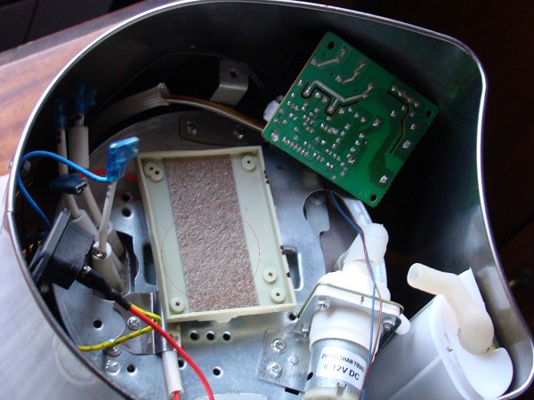
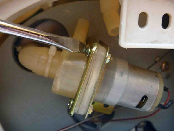
On the side there is a tubular object (water pump). This pump is needed to supply water. In various modifications, the voltage drop across the motor is in the range of 8-24 V.
It is worth noting the electrical board on which the circuit is installed, which is necessary for secondary boiling. In addition, it is required for voltage conversion. Broken contacts on this board can be repaired by hand by simply using a soldering tool.
| Video (click to play). |
In addition to this main board, the device also has a control module. It supports the function of the water supply and reheat keys. Also, indicators are connected to the module, showing in which of the available modes the technician is working at the moment.
In a heating device, the thermostat is of great importance. It is mounted on the bottom or side of the water tank. For situations where the thermostat does not work for some reason, a thermal fuse has been created. It excludes the possibility of overheating and breakage of the thermo-pot when it is accidentally activated with an empty reservoir.
Having found out where all the key elements of the thermopot are located, it becomes much easier to establish the cause of the breakdown and repair the thermopot with your own hands. But it would be more correct to investigate the circuit, to understand all the connections and what parts are to be replaced. In some cases, repairs are impractical, and even specialists do not undertake it.
Let's consider the most common problems and how to fix them.
- The indicator panel does not light up and the device does not function at all. In such a situation, it is necessary to inspect all wires and connections, as well as the thermostat and fuse. If there is more than one breakdown, then it will be more difficult to repair the device with your own hands.
- Only the secondary boil key functions, but the main primary boil is not performed. In such a situation, a thermal switch located in the bottom is checked.
- The main boiling works, but with the secondary boiling, the thermal pot does not work. It is necessary to inspect the module on the main board.
- Boiling does not work, only heating is available. Most likely, the heating component burned out, or the wire broke.
- The water supply does not work. There is a pump malfunction. Often, this burns out the helical element for auxiliary heating, subsequently, no voltage is applied to the motor.
The body of the equipment is fixed with screws that need to be unscrewed by removing the plug from the socket in advance. On the inside you will find a plank that needs to be examined carefully. All kinds of burned out components, no doubt, indicate the specific location of the malfunction. The cord is carefully separated from the device and checked by a tester. If the cause of the problem is in the cable, you can quickly replace it with your own hands.
There are two electronic modules in a standard thermocouple:
- For power supply.
- For management.
Both must be visually inspected for swollen capacitors, blown resistors, unusable fuses, torn tracks. Replace damaged elements with new ones, contacts and soldering are restored by tinning.
But first of all, it is necessary to check the presence of fuses and their integrity. If changing a component does not help, and instead the replaced part also burns out, then the malfunction lies in the electronics, which have failed due to a short circuit.
The resistor value is indicated by colored stripes. A common question is how to find out which side the marking begins and which end.
It is much easier with capacitors - they swell. As a rule, beginners looking for methods to fix a thermal sweat are tormented by the question - what does "swell" mean? To understand, it is enough to see a non-working capacitor at least once.
With diodes, it is always more problematic, however, and they break much less often. You just need to separate the component and test it with a tester at both ends to see if it works.
The torn paths of the electronic circuit should be lightly cleaned by removing the varnish layer from them. Then the surface is tinned and covered with solder. It will work as well as before.
The pump pumps water for supply through the tap in manual or automatic mode. The pump is quite simple, it includes a few simple windings that any beginner can figure out. All contacts must be dialed in pairs. Also, a pump dismantled from the body should be tested by applying a certain voltage to it. The 12 volts needed to test the pump can be obtained from simple batteries or a car battery.
We do not recommend changing metal sheets with terminals for others. Protection against overheating is provided by bimetallic switches. The durability of the apparatus largely depends on the functioning of this element. As a rule, there are more than one thermal switches in the heating element, and one of them controls the characteristics of the liquid, and the second does not allow activation when the tank is empty. In such a situation, the heating element component heats up to a temperature of more than one hundred degrees and breaks the power supply circuit.
To improve the contact of the heating elements switches, a special paste is used, similar to the one applied between the fan and the PC processor.
This sensitive component functions quite simply. When the surrounding space warms up to the set temperature, the contacts of the heating element switch open. But as soon as the temperature drops by 15-30 degrees from this point, electrical conductivity resumes. Unfortunately, it is impossible to find out what type these elements of the heating element belong to, simply by looking at the instructions for the thermopot. However, the surfaces of the elements are always marked so that the optimal replacement can be selected.
As a rule, the manufacturer is not satisfied with a simple overheating protection system and equips the equipment with fuses. These are small tubular elements squeezed tightly against the tank wall or glued to it. When the steel tank heats up to a critical temperature, the heater fuse burns out, and the device will not work unless it is replaced. That is why the equipment should be carefully examined in terms of the presence of such defects.
Also, with the help of a tester, the operability of the bimetallic contact is checked.Before starting the test, the heating element should be evaporated.
When the spirals of the heating components burn out, it is simply unprofitable to repair the equipment. The tank is too complex to disassemble on its own, and the insulation and cables are not cheap enough.
After completing the repair work, the safety of the device should be tested. For this purpose, the resistance between the plug and the reservoir, and between the plug and the outer casing should be determined. In a normal situation, it must be infinite.
Electric kettles - thermoses, or thermopots, serve regularly for 2 - 3 years, then usually fail. The main reasons for this: they stop boiling water, do not pour boiling water, and because of the flow of water. There are many materials on the Internet about the repair of thermocouples, but there are almost no schemes. The article briefly describes the models of thermopots, the diagrams of which are copied from the products, the malfunctions of which the author encountered during the repair. The article provides examples of circuit solutions used in most models of modern thermopots, despite the large number of clones produced by various companies.
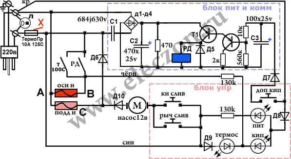
In the given diagrams, the designations of most of the parts correspond to those indicated on the boards. For different models of thermocouples, the secondary power supply circuits and control units are very different. All thermo pots have a stainless steel boiling tank. In its lower part there are fixed thermoelectric heaters, heating elements, usually two of them, for boiling and heating water, in this case they are in one block, which has three outputs. A thermal switch for a temperature of 88 - 96 degrees C or a thermal sensor is fixed at the bottom of the tank, giving a signal to turn off the heating element of the boiler when the required water temperature is reached. On the side wall of the tank, a thermal switch connected in series for a temperature of 102 - 110 degrees C and a fuse FU for 125 degrees C / 10A, placed in a silicone tube, are fixed. They cut off the power supply to the thermal pot when the temperature of the boiling vessel rises due to lack of water or in the event of a short circuit. To supply hot water in thermopots, the same type of DC motors for a voltage of 12 V, with a centrifugal pump, are used.
Most of the parts for thermal pots are located on two boards. The control board, on which the control buttons and LEDs are located, is located in the upper part of the case. The main board, on which most of the power connectors, control units, relays, sources and secondary voltage stabilizers are located, is located in the lower part of the case under a container for boiling water. Both boards are interconnected with wire harnesses with connectors.
The diagram of the Elenberg TH-6030 thermo-pot, [1] is shown in Fig. 1. Earlier, in 2014, the author posted it on the go-radio site, so a link to this site is given. The TN-6030 circuit is quite simple and completely analog. Constantly through the heating element for heating water EK1 and the diode VD9, a pulsating current flows in only one direction, therefore the resistance of this heating element is two times less than that of a similar heating element of the same power in other models, where it is powered by alternating current. When the electric motor is turned on, a constant pulsating current of a different polarity begins to flow through it and the VD10 diode, up to 150 mA, and an alternating current flows through the heating element EK1. Automatic switching on and off of the heating element for boiling water EK2 is performed by the SF1 thermal switch. Forced switching on of the heating element EK2 for up to 2 minutes is made by contacts K1.1 of relay K1. For transistors VT1 - VT2 of the control stage of relay K1, a constant voltage of 14 V, stabilized by the chain R3 and VD6, is supplied from the diode bridge VD1 - VD4. A frequent malfunction of this model of a thermopot is the burnout of the contacts of the SF1 thermal switch, because the entire current of the heating element EK2 passes through it. Replacing the thermal switch is not difficult, you need to unscrew two screws on the flange, and rearrange the two power connectors. Detailed videos of this replacement are available on the Internet.
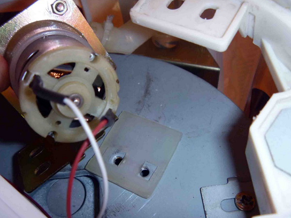
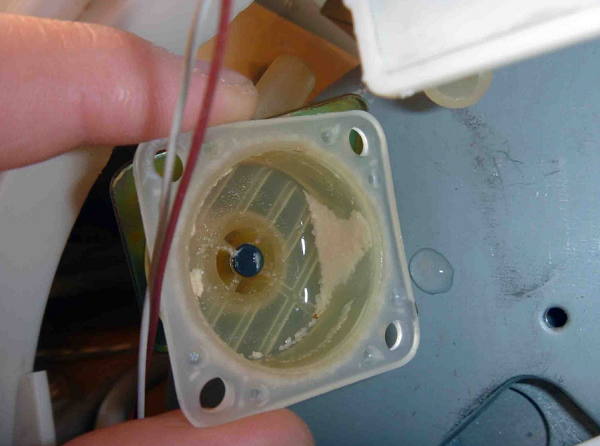
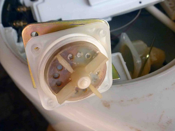
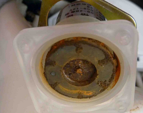
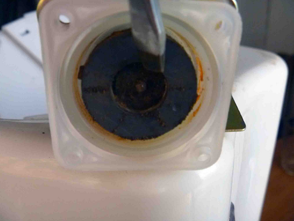
Another malfunction, poor operation of the hot water supply pump.Its cause is an increase in the friction of the rotor axis of an electric motor operating at an elevated temperature due to a deterioration in the quality of the lubricant. The magnetic clutch of the pump consists of a magnetic disk, put on the rotor shaft of the electric motor and the pump impeller, put on the axle shaft in the pump casing cover. A magnetic disk is also fixed at the base of the impeller. An airtight gasket is installed between the two magnetic disks. Rice. 2.
The author lubricated the bearing points of the rotor at the ends of the electric motor housing with ordinary spindle oil. Helped for a couple of months. It is difficult to get to the front point of support, you had to disassemble the pump and pour oil under the magnetic disk, and turn it with your finger, at this moment the electric motor is in an upright position so that the oil flows into the right place. The remaining oil is drained over the edge. It is not necessary to remove the disc from the rotor axis, a couple of removals and it will not stay on the rotor axis. It is easier to immediately replace the motor with the pump.
Water leaks in thermopots are rare, usually due to mechanical damage. Once the reason for the appearance of water under the kettle was an inconspicuous crack in the upper part of the plastic case, under the lid, running along the rim of the container for boiling water. Steam penetrated this gap, which then condensed on the inner surface of the walls of the case, the plastic crumbled along the crack. That kettle was beyond repair.
Photo of the VT-1188 main board. Rice. 4.
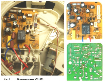
The diagram of the VT-1191 thermo-pot is shown in Fig. 5. The secondary voltage source for control units is pulsed, made on a VIPer 12A microcircuit according to a transformerless circuit. A constant voltage of 18 V at its output is filtered by capacitors EL3, C3 and a choke L2, then the zener diode ZD2 is lowered to 12 V. The control circuit works on the ic1 processor, there is no marking on its case, there is only a label indicating the model of the thermo-pot. A voltage of 5 V to ic1 is supplied from a regulator on transistor Q4 and a zener diode ZD3. There are two heating elements in the VT-1191 thermo-pot: EK1 for boiling and EK2 for heating water. Contacts K1,1 of relay K1 alternately connect the conclusions of one of them to the network, depending on the voltage at pin No. 5 of ic1, which, through the CN1 connector, LED HL2 and R7, goes to the base of the transistor Q1. A small base current of transistor Q2 flows through the SF2 thermal switch, so SF2 is connected to the board and pin no. 4 of ic1 with a low current connector. The electric motor is turned on by the Q3 transistor when a "+" appears on pin # 3 of ic1. The malfunction of the thermo-pot manifested itself in the fact that it did not boil or pour water, only the green indicator HL3 was on. The cause of the breakdown was the failure of the ic1 processor.
There are many tips for repairing thermo pots, but I will add two more:
1) Take pictures of the entire process of disassembling and repairing the kettle. This will then facilitate its subsequent assembly and especially, the installation of power connectors. (Fig. 6).
2) If the housings of the low-current connectors installed on the boards are even slightly loose in their places, these housings must be glued to the board and the contacts must be soldered. Violation of the connector contacts after repair and assembly of the thermal pot can lead to new malfunctions.
Thermopot is a mixture of a teapot and a thermos. To maintain a certain temperature of the liquid in the device, a heating function is provided. Despite the rather reliable design, the device breaks down over time, and the question arises: is it possible to repair the thermopot with your own hands?
Before you start looking for the reasons that caused the malfunction in the device, it is advisable to know a little about its device. A thermopot consists of a plastic or metal case, inside which there is a metal container for water. The device is closed with a lid with controls.
In any thermo-pot there are 2 heaters: one for boiling water, and the second for maintaining the desired temperature regime. To control the heating of the liquid to a certain value, the device is installed thermostat... The latter is of 2 types.
- Stepless - characterized by smooth regulation of the water temperature in the range from 60 to 100 degrees.
- Stepwise - the temperature regime is adjusted according to fixed temperature values, for example, as in the VITEK VT-1187 GY thermo-pot, Saturn ST-EK8032, as well as in the MYSTERY MTP-2403 device
Thermopots always have at their disposal several heating control modes. The more modes there are, the more flexible the device can be controlled.
But practice suggests that in most cases 3 modes are enough to control temperature indicators. In inexpensive models such as Magnit RTP-013 and MAGNIT RTP-002, only 1 temperature setting is available, which only allows you to boil water.
Also, the thermopot is equipped with an electronic board (control module) and electric pump (pump) for supplying heated water from the container. To supply heated water to the cup, there are several modes: manual filling, auto-filling and filling with a lever on the spout. Such filling functions are available, for example, in the Polaris pwp 4012d or Saturn ST-EK8034 NEW aggregate.
The most common causes of breakdowns are the following parts of the device:
- network wire;
- control module;
- water pump;
- electric heaters;
- thermal switch.
Before you repair the thermo-pot with your own hands, you should disconnect it from the network. After that, in order to “ring out” the wire of the device with the tester, it must be disconnected. To do this, unscrew the screws on the bottom of the device and remove it. You will see the terminals to which the power cord... Unplug the cord and start “ringing” it with the tester. If the cord is in order, you can proceed with further troubleshooting.
If you find that on your device button does not work or all keys, the cause of the problem may be a failed control unit. It is not recommended to repair it on your own, since it is necessary to have certain knowledge in radio electronics. It will be better if a service center will repair the thermos kettle.
If, after turning on the device, it does not boil water, while all heating modes, as well as automation, are working, then these symptoms indicate that the heater may have burned out or the thermostat has failed.... To find out, you need disassembly of the unit.
-
Empty the container and turn the device over. At the bottom, you will see screws that need to be removed.


Unscrew the PCB and set it aside.


In different models of units, the type of heating elements may differ.Their location may also vary. But the algorithm for disassembling the device, in most cases, is similar. To learn more about how to change the heaters, you can watch the video.
If the thermopot does not pump water when trying to pour hot liquid into the cup, then, most likely, the pump does not work, due to its failure. To get to the pump, you will need to disassemble the device as described above. After removing all parts of the bottom, you will see the pump.
Next, do the following.
- To easily remove the pump, disconnect one of the tubing connected to the pump. If the tubes are clogged with limescale, it is recommended to remove and clean them.
- Separate the pump from the housing and be careful not to lose the silicone gasket.
- After that, unscrew the fasteners connecting the motor to the impeller to the pump housing.
- After disconnecting the pump housing and the electric motor, you will notice scale build-upthat interferes with the rotation of the impeller.
- Also, if you remove the impeller (it is she who is responsible for the water supply), you can find clogged magnetto be cleaned of dirt.
If, after removing all the contaminants, the pump does not turn on and there is no water supply, then you will need to purchase a new pump, since these signs indicate a burnout of the electric motor winding.
Sometimes a situation arises when the thermo-pot does not turn off and boils water constantly... Or vice versa: you have poured water, the device heats it up, but turns off when the liquid is not boiling yet. Why is this happening? This malfunction can occur when the thermal switches are faulty. They can be found on the bottom and sides of the tank. For better contact with the surface, a special thermal paste is used.
The thermal switch located at the bottom of the tank is attached to it with two screws. Sometimes a manufacturer, especially a Chinese one, applies little thermal paste, because of which the thermostat starts to work incorrectly: the device may not turn off for a long time when boiling water.
To test the thermostat for operability, it is necessary to disconnect it from the tank body, and remove the wires from the terminals. In the normal state (no heating), the relay is in the “on” position. If you check it with a tester, the device will show a resistance of 0 Ohm.
Next, you should connect 2 wires to the switch and immerse it in water brought to a boil. Now measure the resistance again. If the device shows infinity, it means that the switch has tripped and it is functioning normally. If the sensor is not working, then you should purchase a new one and replace it. You can watch the following video about replacing the thermal switch.
Above, some breakdowns of the thermos kettle were considered, which can be completely eliminated without the involvement of a specialist. In other cases, the unit should be taken to a specialized service center for repair. But before you hand over the device for repair, ask how much it will cost you. Most often, from a financial point of view, repairs are not justified, since its cost will be within the price of a new thermo-pot.

