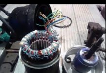
In detail: bosch injection pump device and do-it-yourself repair from a real master for the site my.housecope.com.
There is no more complex and critical unit in a diesel engine than the fuel injection system, more precisely, its main part - the high pressure fuel pump. Many mating parts, highly loaded units, the presence of a precision dosing system, make the repair of the injection pump a difficult task even in service conditions. It is all the more difficult to repair the high pressure fuel pump of a diesel engine with your own hands.
In automotive technology, almost everything is repaired, except, perhaps, individual oil seals and cuffs, the repair of which is impossible without special materials. The complexity of setting, diagnosing and repairing the injection pump requires the employee to have the skills to work with precision mechanics.
It is simply impossible to adjust according to the factory parameters, without a special diagnostic stand for the repair of the injection pump. During the diagnostic study of the injection pump, it is necessary to check:
- cyclic supply of the high-pressure pump, in the entire range of revolutions of the injection pump shaft, at start-up, and after cutting off the fuel supply;
- stability of the developed pressure;
- uniformity of the injection pump delivery to the fuel injector.
Even having access to a diagnostic stand, and having studied the issue of repairing a high-pressure fuel pump using numerous videos, it is very difficult to qualitatively check and evaluate its work.
In heavy diesel engines, plunger, in-line injection pumps are used. In maintenance and repair, such devices are more difficult, since they require special equipment for its disassembly, therefore we will not consider such high pressure fuel pumps and their repair.
In a passenger diesel engine, a distribution type injection pump is almost always used. Unlike in-line pumps, in a distribution pump, the force is transmitted to the plunger using a profiled cam washer. The design of the injection pump turned out to be more compact, but it is hardly simpler to expect to carry out its repair on the knee.
| Video (click to play). |
The most famous and affordable is the Bosh VP44 injection pump. Often, the need to repair the pump internals arises when:
- poor traction and incomplete combustion of fuel even under ideal conditions - in the absence of load and a thoroughly warmed up engine;
- a sudden failure and stoppage of a diesel engine under load, which is called “death on takeoff”. Usually the scanner in such cases diagnoses the code P1630 and P1651.
- the appearance of a diesel fuel leak in the area of the gland seal of the central shaft of the injection pump.
Therefore, we will restrict ourselves to the issue of repairing the injection pump with our own hands by replacing the seals and eliminating the scoring of the working surfaces of the parts.
Before disassembling the pump drive shaft seal, try to move it radially. If play is felt with your hands, it is possible that the reason for the leakage of fuel is the wear of the working surface of the shaft or requires repair of the bearing.
A large number of split planes and mating surfaces of parts required the use of a large number of seals and glands. As a rule, they are made of quality material and last long enough until they are damaged during repair or maintenance. In this case, standard repair kits are used for DIY repair of Bosch injection pumps.
It is quite easy to replace the seal on the shaft position sensor and on the automatic injection timing during repairs. For a better fit, you can drip a few drops of spindle or engine oil onto new rings and rubber bands.
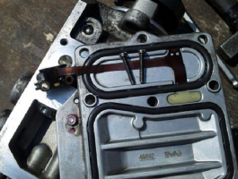
For preventive repair of a Bosch injection pump with your own hands, you will need to disassemble the pump in approximately the following order:
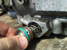
- remove the metering valve from the end of the injection pump. To do this, unscrew the four screws of the pressure plate, carefully release the cable of the injection advance valve. By removing the three screws securing the metering valve, you can carefully remove it from the seat;
- by unscrewing the fastener on the top cover, you can remove the control board and gain access to the electronics;
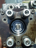
- we set the position of the shaft, as shown in the photo, remove the camera and get access to the insides of the injection pump;
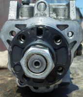
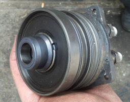
- after dismantling the bearing using a special puller, we get the opportunity to study the potential culprit for the poor performance of the injection pump - the piston of the injection advance unit. There is often surface wear and edge scuffing on the part. You can try to make repairs by polishing the surface, replacing the whole part is much more expensive.
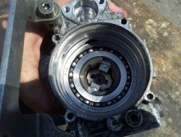
After the repair, the assembly is carried out in the reverse order with the washing of the parts with diesel fuel.
Often, in addition to scoring, on the surface of the pistons there is another reason why the injection pump does not develop the required pressure. This can be due to debris, films or wax build-up on the filter screen inside the pump. There is a mesh on the side of the inlet pipe. Rinsing the channels is a troublesome and ineffective business, it is easier to remove the mesh and blow it with compressed air.
Torn pieces of debris can jam the plunger piston or even break or break the pump drive shaft. Therefore, cleaning should be done very carefully to avoid contamination of the internal cavities of the pump.
Among the many reasons for the failure of the electronic "liver" of the injection pump, the most common is the breakage or burnout of the contacts of the control board and the failure of power transistors. If the knowledge and skills of working with electronic devices allow to carry out a "continuity" of the transistor performance and repair, it is worth trying to identify the cause and replace the culprit with a serviceable element.
To check the condition of the "culprit", you need to carefully open the black cover, which is tightly seated on the rubber seal with screws. It should be removed carefully so as not to damage the seal itself.
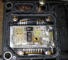
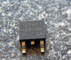
The reason for the failure of not only the transistor, but also the entire board could be air trapped in the cavity due to poor performance of the drainage system or the check valve. Often, they try to eliminate the airing by spinning up with a starter, hoping to pump diesel fuel into the high-pressure fuel pump in this way. At this moment, the transistor is open and loaded as much as possible, which leads to intense heating. In an air environment, with poor heat dissipation, it will inevitably burn out. In some German cars there is a protection that prevents an attempt to start the engine in the absence of fuel in the highway. For this, a fuel sensor in the tank is used.
Failure of the transistor can be established by "dialing" a tester or by its appearance. The best option for repairing such a malfunction would be to replace the entire control board. Perhaps it is more expensive than soldering, but it will give guaranteed quality and stable operation of the injection pump after repair. As a last resort, give the board and the transistor for soldering to electronics specialists.
When installing and reassembling after repairs, check the tightness of all fasteners.
If during the audit you did not make rash and unreasonable replacements of parts, the assembled pump should work with approximately the same parameters as before. Bosch EPS-815 stand is used as a standard for testing and adjusting injection pump after overhaul.
The video shows how to raise the plunger pressure in a Bosch VE injection pump:
The injection pump number 059 130 106D was installed on cars:
Volkswagen Passat B5.5 / Volkswagen Passat B5.5 (3B3) 2001 - 2005
Volkswagen Passat Variant B5.5 / Volkswagen Passat Variant B5.5 (3B6) 2001 - 2005
Volkswagen Passat B5 / Volkswagen Passat B5 (3B2) 1997 - 2001
Volkswagen Passat Variant B5 / Volkswagen Passat Variant B5 (3B5) 1997 - 2001
Audi A4 B5 / Audi A4 B5 (8D2) 1995 - 2001
Audi A4 Avant B5 / Audi A4 Avant B5 (8D5) 1996 - 2002
Audi A6 C5 / Audi A6 (4B2) 1997 - 2005
Audi A6 Avant / Audi A6 Avant (4B5) 1998 - 2005
information is suitable for repairs and other cars.
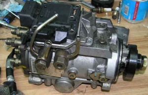
Hello everyone! I decided to write a report on self-repair of the Bosch VP44 injection pump, number 059 130 106D, auto Audi A8 D2 2.5tdi V6, but this pump was not installed anywhere, Audi A4, A6, VW, BMW, Opel, often breaks down on trucks - so I think the information will not hurt.
I had no experience with high-pressure fuel pumps - so I bombarded specialists with questions on various forums - thanks to everyone who helped with advice!
A big role was played by the report of the owner of the Opel Vectra - Mitrofana (Thank you). The progress of the disassembly process is displayed there.
I want to tell you about my experience and my own “rakes” so that no one would jump on them again.
So, after pumping with a pear or something from the nozzle pipes, nothing presses when scrolling with the starter - it means you have problems with mechanics: the most likely option is damage to the membrane (or cutting rings), the second option is a defect in the booster pump ... You will see all this later in the photo.
Anyone who has everything working properly - here you can view the high-pressure fuel pump from all angles, incl. his most intimate places
To begin with, while the pump is on the machine, we set the timing and injection pump to the “base” position so that the hole for the stopper coincides with the hole on the pulley (we shine a flashlight), you can rotate the timing either by the crankshaft or by the camshaft (but with a force of no more than 75 Nm (! ), smoothly, with pauses, or with a gearbox, hanging out the muzzle, rotating the wheel. Then loosen the nut by 27mm of the gear wheel, put a clear mark on the shaft and the gear wheel. We may need it when reassembling. The tooth itself. The wheel sits firmly on the "cone "- even without a nut, it won't move a single gram, you don't need to press it yet, so far we only need a mark with an awl:
The decision on whether to compress it or not will be made later (so as not to do unnecessary work).
Then we unscrew the pump from the auto - we close the fitting with something and thoroughly rinse it with a “karcher”, then blow it in places with a carb cleaner and blow it with compressed air so that there is less dirt during disassembly:
We unscrew the "brains" and 2 e-mail. valve (details at Mitrofan), for this we need Torx 10,25,30 (later another T20 is possible). Before unscrewing, knock on the Torx with a small hammer, if it does not work, it is better to continue knocking, because when you break the edges, you will have to drill and drive in the “M” bit.
When pulling out the central valve (with a screwdriver as a lever), you need to make sure that it comes out without skewing, if it skews, push it back and again try supporting it from below.
Then we bring the gear wheel (which is still firmly sitting on the cone) to the mark into which the stopper is inserted (or, as for a collective farm, a 6mm drill), unscrew the T50 bolt, remove the washer under it and tighten it all the way, thereby blocking the movement of the shaft, the stopper take out:
In this case, the back will be in this position:
Further, to remove the distributor head according to Mitrofan, we burst and swing with screwdrivers, but I, so as not to spoil the al. the body simply rested with a screwdriver and knocked down with a hammer:
We remove the distribution head and see the very defect due to which the pressure disappeared - damage to the outer plastic part of the membrane:
If you saw such a picture (or just a crack), then there is no need to disassemble further - we change the membrane and rubber rings and put them back together. Membrane repair kit Bosch 1 467 045 032. But there are important nuances, read here
Since I did not immediately notice due to inexperience, I disassembled further:
Further, to remove the bearing according to Mitrofan, we pull it with a thick wire, I just spread the newspaper on the floor and hit it with the body - by inertia the bearing and 2 washers came out:
Then you need to unscrew the plug, wrap the top with paper or a rag and pull out with pliers:
With drifts or something handy, we turn the cam washer and the piston to the position at which the cool. the washer will move up (in the photo you need to turn it a little clockwise and it will rise):
After removing the cooler. washers - we take out the piston - this is how it looks from all sides (if it comes out badly, you can swing it with drifts for 2 holes, which are in the photo at the top left, but do not stick it deep into the hole):
Now we press the gear wheel off the shaft (while the shaft is "pressed in" Torx50, which was mentioned above, otherwise, when removed, the shaft will shoot like a bullet - both the shaft and the housing can be damaged). You will need a GOOD puller, the effort is HUGE, we put good pieces of rags under the puller's paws, so as not to leave “jammed”.
After pressing, we loosen T50 and take out the shaft.
... and the puck (what's underneath). The booster pump remains in the housing.
Now, using T20, unscrew the bolts (you need a long and thin T20, preferably):
It is desirable to “shake it out” by hitting the body on the newspaper - then it will fall out “assembled”. If you try to push from behind with your fingers, it will most likely fall out "in parts", this is bad:
As they say, it is undesirable to confuse the blades in places, otherwise they can wedge at revolutions.
Another photo of him:
It is serviceable, the only thing there is a small defect - chipping, but this is not criminal:
The booster pump was taken from the spare donor pump, it fell out “assembled”, we rinse very well. carba:
Then the empty body was washed with "Karcher" (without bringing it close to the channels), then och. Carba dried through channels and compressed air. Purity:
Install the booster pump (donor) in place:
We put the washer and insert the shaft (in the photo the washer hangs on the shaft):
The gear wheel is ready for installation:
Align it according to our scratch mark with the shaft, then rotate it until the hole for the stopper is aligned and block T50:
Slightly (!) Fill the tooth. the wheel onto the shaft, lightly tighten the nut by 27mm. We put catalogs and a tooth damper on the table. wheels to position the injection pump conveniently for further assembly.
In this case, the picture is as follows, the shaft is locked in the “basic” position:
The piston was taken from the donor pump, the scratches were slightly sanded with the P800, 1500, 2000 legs. It is advisable to grind the sleeve itself in the injection pump housing with P2000 (but this is before washing).
As you can see on the left - the piston ring interferes with the assembly - just wrap the piston with plastic wrap, squeeze it with your fingers and put it on:
Place the piston so that the cam washer is “filled” into it (yellow arrow). The second point of connection is cool. washers - black arrow:
And here is the cam washer itself, these 2 pins must be “inserted” into the holes:
“Diesel Market"- Spare parts for engines: pistons, rings, liners, gaskets, sprayers, candles, plunger pairs, high pressure fuel pumps
AUTOWELT - spare parts for engines of Japanese and European cars
DENSODIESEL - the central distributor of DENSO for diesel injection systems in Russia
Single plunger fuel distribution pumps ve bosch fuel pump design ve general pump arrangement bosch ve


SINGLE PLUNGER DISTRIBUTION FUEL PUMPS VE
The design of the fuel pump BOSCH VE
General device of the BOSCH VE pump
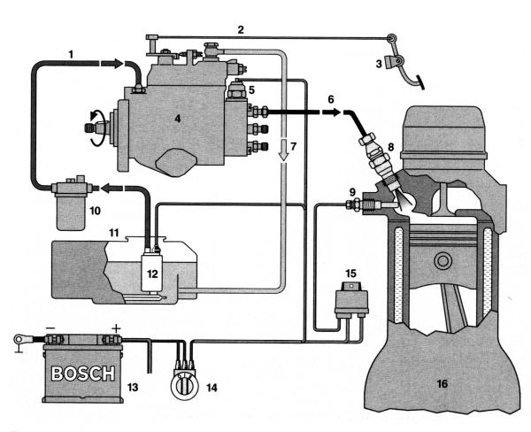
A schematic diagram of a diesel fuel supply system with a single-plunger distribution injection pump with an end cam drive of the plunger is shown in Fig. ...
Rice. Schematic diagram of the fuel supply system of a diesel engine with a single-plunger injection pump:
1 - low pressure fuel line; 2 - thrust; 3 - fuel supply pedal; 4 - injection pump; 5 - electromagnetic valve; 6 - high pressure fuel line; 7 - fuel line of the drain line; 8 - nozzle; 9 - glow plug; 10 - fuel filter; 11 - fuel tank; 12 - fuel priming pump (used for long-distance highways; 13 - storage battery; 14 - ignition switch; 15 - control unit for glow plug activation time; 17 - diesel
The fuel pump delivers a strictly metered amount of fuel under high pressure to the diesel cylinders at a certain point in time, depending on the load and speed. Therefore, the characteristics of the engines significantly depend on the operation of the injection pump. The main functional blocks of the VE fuel pump are shown in fig. and represent:
1) a low pressure rotary vane fuel pump with a regulating bypass valve;
2) high pressure unit with distributor head and metering sleeve;
3) automatic speed controller with a system of levers and springs;
4) an electromagnetic shut-off valve that cuts off the fuel supply
5) an automatic device (machine) for changing the fuel injection advance angle.
Fig. 9. Fuel pump diagram - Bosch VE
The distributor injection pump VE can also be equipped with various additional devices, for example, fuel correctors or a cold start accelerator, which allow the injection pump to be individually adapted to the characteristics of a given diesel engine. In more detail, the device of the VE fuel pump is shown in Fig.
Fig. 10. Fuel pump diagram - Bosch VE:
1 - pump drive shaft; 2 - bypass valve for internal pressure regulation; 3 - fuel feed control lever; 4 - weights of the regulator; 5 - fuel drain jet; 6 - full load adjustment screw; 7 - transmission lever of the regulator; 8 - solenoid valve for stopping the engine; 9 - plunger; 10 - central plug; 11 - discharge valve; 12 - metering sleeve; 13 - cam disk; 14 - automatic fuel injection advance; 15 - roller; 16 - clutch; 17 - low pressure fuel priming pump
The drive shaft 1 of the fuel pump is located inside the high-pressure fuel pump housing, the rotor 17 of the low-pressure fuel pump and the gear wheel of the drive shaft of the regulator with weights 4 are installed on the shaft. The injection pump is carried out by transmission from the crankshaft of the diesel engine, gear or belt. In four-stroke engines, the frequency of rotation of the injection pump shaft is half of the rotational speed of the crankshaft, and the operation of the distribution injection pump is carried out in such a way that the translational movement of the plunger is synchronized with the movement of the pistons in the cylinders of the diesel engine, and the rotary movement ensures the distribution of fuel among the cylinders. The translational movement is provided by a cam washer, and the rotary movement is provided by the fuel pump shaft.
Automatic speed controller. (block 3 in the figure) includes centrifugal weights (Fig.), which through the regulator clutch and the system of levers act on the dispenser 9 (Fig. 10), thus changing the amount of fuel supply depending on the speed and load modes of the diesel engine. The injection pump housing is closed from above by a cover in which the axis of the control lever associated with the accelerator pedal is installed.
The automatic fuel injection advance (block 5 in Fig. 9) is a hydraulic device, the operation of which is determined by the fuel pressure in the inner cavity of the injection pump, created by a low-pressure fuel pump with a control valve 3 (Fig. 10). In addition, a predetermined pressure level inside the injection pump housing is maintained by a throttle 5 in the fitting for the excess fuel to exit the injection pump housing.
Rotary vane booster pump and low pressure system
The low pressure fuel pump is located in the injection pump housing on the drive shaft and serves to take fuel from the tank and supply it to the inner cavity of the pump housing. A schematic diagram of a low pressure fuel pump with a low pressure valve is shown in Fig. 11.
Fig. 11 Low pressure fuel pump
1-annular cavity; 2-rotor; 3 blades; 4-shaft;
5-way control valve; 6-valve body; 7-screw plug; 8-spring; 9-plunger
The pump consists of a rotor 2 with four blades 3 and a ring 1 in the injection pump housing, located eccentrically on the outer side of the rotor. When the latter rotates, the blades under the action of centrifugal force are pressed against the inner surface of the ring, thus creating chambers between them, from which the fuel under pressure flows through the channel into the inner cavity of the high pressure pump housing. At the same time, part of the fuel enters the inlet of the bypass control valve 5 and, if it opens, is bypassed to the pump inlet. The body 6 of the bypass control valve is threaded into the body of the injection pump, inside the body there is a piston 9, loaded with a spring 8 calibrated to a certain pressure, the other end of which rests against the plug 7.If the fuel pressure is higher than the set value, the valve piston 9 opens a channel for bypassing some of the fuel to the suction side of the pump. The pressure of the beginning of the opening of the bypass valve is regulated by changing the position of the plug 7, i.e. spring preload value 8.
An important role in ensuring the normal operation of the diesel engine is played by a drain throttle installed in the fitting in the high-pressure fuel pump cover (item 5 in Fig. 10). A jet with a diameter of about 0.6 mm, through which the fuel goes to drain, maintains the required fuel pressure in the inner cavity of the injection pump housing. Obviously, the size of the throttle is coordinated with the operation of the bypass valve.
The bypass valve 5 (Fig. 11) in combination with the drain throttle 5 (Fig. 10) provides a predetermined dependence of the fuel pressure difference in the high pressure fuel pump housing and at the low pressure pump outlet on the high pressure pump shaft speed. The amount of fuel supplied by the low pressure pump is several times greater than that supplied to the diesel cylinders. The fuel pressure in the inner cavity of the injection pump housing affects the position of the piston of the injection timing machine, changing the injection timing in proportion to the engine speed.
Distributor plunger and high pressure line
The main element that creates high fuel pressure in the high pressure fuel pump and distributes the fuel through the cylinders of the diesel engine is plunger 7 in Fig. 10, which performs a reciprocating and rotary motion according to the following scheme:
engine -> injection pump shaft -> cam washer -> plunger
The fuel path through the pump and the elements that ensure the operation of the distributor plunger are shown in Fig. 12.
The principle of operation of the pump is explained in Fig.
Fig. 12 Fuel flow diagram in the high-pressure fuel pump:
1 - direction of rotation of the roller; 2 - roller; 3 - cam disk; 4 - plunger; 5 - fuel supply sleeve; 6 - camera; 7 - channel for supplying fuel to the injector; 8 - distribution groove
The protrusions-cams of the cam washer 3 are in constant contact with the rollers 2 mounted on the axles in the stationary ring 1. When the cam washer rotates, each cam, running onto the roller, pushes the plunger to the right, and its return to its previous position is carried out by two springs of the injection pump unit.
The number of cams on a cam washer, like the number of high pressure line fittings with discharge valves, corresponds to the number of cylinders in the engine, usually four or six. The return springs of the plunger, in addition, prevent the rupture of the kinematic connection between the cam and the follower roller at high accelerations. Providing the reciprocating movement of the plunger, the cam washer in the shape of the protrusions-cams also determines the stroke of the plunger and the speed of its movement and, therefore, the characteristic, pressure and duration of injection. All these parameters, in turn, are determined by the shape of the combustion chamber and the peculiarities of the working process of a given diesel engine and must therefore be coordinated. For this reason, for each type of diesel engine, a tape of the profile of the cakes is calculated, which is "superimposed" on the front surface of the cam washer installed in the injection pump. Therefore, the cam washer of this pump is a non-interchangeable part, individually corresponding to a given type of diesel engine.
Injection advance clutch. The earlier ignition with an increase in the crankshaft speed increases the power of the diesel engine. When the engine speed increases, the injection starts earlier.
Rice. Injection advance clutch:
Rice. a - starting position; b - working position; 1 - injection pump housing; 2 - a ring with rollers; 3 - roller; 4 - finger; Channel 5; 6 - cover; 7 - piston; 8 - support; 9 - spring
The injection pump plunger creates high fuel pressure and distributes it through the cylinders during the following functional stages of the fuel supply process: fuel intake, active piston stroke and fuel injection (injection), supply cutoff, the process of closing the discharge valve and unloading the high pressure line.
The fuel supply processes in the distributor head are shown in fig. ... In the upper diagram in Fig. a shows the position of the plunger in the extreme left position (dead center). In this case, the high-pressure chamber 3 contains the fuel that was previously supplied through the inlet channel.
When the plunger moves to the right, fig b, the fuel starts to compress, while the inlet 7 is disconnected from the fuel inlet slot 8, and the fuel under working pressure flows through the central channel of the plunger into the corresponding outlet channel of a certain cylinder. Under pressure, the discharge valve opens and the fuel flows through the high pressure line to the injector.
The fuel supply ends as soon as the feed cutoff hole 6, located transversely in the plunger, goes beyond the metering clutch (Fig. C). In this case, the fuel comes out into the inner cavity of the pump and the pumping stops.
With further rotation and movement of the plunger to the left (Fig. D), the distribution slot 2 is disconnected from the channel 4, the inlet is aligned with the corresponding slot 8 in the plunger, and due to the created vacuum, the fuel enters the high-pressure chamber 3 and the central channel. The process of intake and subsequent injection of fuel occurs during a plunger rotation of 90 ° in a four-cylinder diesel, 72 ° in a five-cylinder and 60 ° in a six-cylinder.
1 - plunger; 2 - distribution groove; 3 - camera; 4 - outlet; 5 - fuel supply sleeve; 6 - control hole
Diesel boost pressure corrector. The automatic anti-smoke corrector or diesel boost pressure corrector (LDA) is used to match the fuel flow supplied to the diesel cylinders with the air flow supplied by the compressor, thus eliminating engine smoke. The need to install the specified automatic device is determined by the change in the air density in the cylinders of a turbocharged diesel engine, depending on the operating mode of the turbocharger. The work of the corrector is especially necessary in the diesel acceleration modes, when the amount of fuel supply increases much faster than the air flow rate, while the excess air ratio decreases, and the operation of the diesel engine is accompanied by smoke.
The design of the boost pressure corrector installed on the upper cover of the pump casing is shown in Fig.
Rice. The scheme of work of the corrector with a turbocharger:
a - the position of the membrane at increased boost pressure; b - the position of the membrane with insufficient boost pressure; 1 - lever-stop of the corrector; 2 - stock; 3 - membrane; 4 - supply of vacuum from the intake manifold; 5 - spring; 6 - fuel drain jet: 7 - rod; 8 - adjusting screw for maximum flow; 9 - increased feed stroke; 10 - metering sleeve; 11 - plunger; 12 - starting lever; 13 - power lever
If the turbocharger malfunctions, then the automatic LDA device, i.e. the boost pressure corrector turns out to be in the initial position on the upper stop (Fig. b), ensuring that the diesel engine operates without smoke. The value of the maximum fuel supply for this engine is regulated by screw 8 installed on the high-pressure fuel pump cover.
Fuel pumps Bosch VE and high-pressure fuel pumps VE ZEXEL (Diesel Kiki) and Nippon Denso, produced under license from Bosch, are widely used and are installed on diesel engines of European and Japanese cars Audi, VW, BMW. Volvo, Peugeot. Ford, FIAT, Mazda, Nissan. Mitsubishi and others.
The nomenclature of VE fuel pumps is determined by the type of diesel engines on which they are installed, and the basic data of the pump are reflected on the nameplate of the company shown for one pump as an example in the figure.
Rice. Nameplate with model designation of injection pump VE
The pump brand VE 4/9 F2250R12 stands for the following:
- V - distribution pump;
- E - denotes the injection pump family;
- 4 - the number of engine cylinders;
- 9 - diameter of the pump plunger, mm;
- F - designates the type of regulator - centrifugal;
- 2250 - rated speed of the pump shaft, min-1;
- L - left-hand rotation pump (R - right-hand rotation);
- 12 - performance index (for this diesel engine).
Additional digital designations on the plate are company indexes, for example, 0 460 494 001 stands for 0 - production index, 460 - product class, 4 - designates a VE type pump, 9 - plunger diameter index. 4 - the number of diesel cylinders, 001 - serial number, which can be changed in production.
In Japanese-made VE fuel pumps, the abbreviation "NP" is added to the designation, for example, VE 4/8 F 2500 LNP 347.
In addition, the company (ZEXEL) may be indicated on the plate, and the same name is cast together with the pump casing.
The index of the contractor in the designation of the pump can be specified depending on the configuration, so for the VW "AAZ" diesel we have:
- Bosch VE 4/9 F2300 R 432 - car without air conditioning;
- Bosch VE 4/9 F2300 R 432-4 - with air conditioning.
Despite the wide range of VE pumps and some design differences, there are general methods for checking and adjusting the high pressure pump in question. Below are some of the techniques for the simplest checks of fuel equipment in the event of a malfunction of the diesel engine.
If there is a skip of flashes in individual cylinders of a diesel engine, uneven operation and a loss of power associated with this malfunction, then to determine the cylinder that is working intermittently, the method of their sequential shutdown at the mode of the minimum idle speed can be applied. To do this, unscrew the nut fastening the high-pressure pipe to the injector by half a turn and determine the presence or absence of changes in the engine operation by ear or using a tachometer. In the absence of changes in operation, this cylinder is the cause of uneven operation and, therefore, a more detailed check is required (injectors, compression, etc.).
Exhaust gas smoke analysis is useful in determining the causes of malfunctions in a diesel engine.
Rough operation and loss of power can be caused by dirt or air leaks in the fuel intake lines. The presence of bubbles of the latter at the inlet can be determined by installing a transparent tube on the suction line.
If the diesel engine does not develop the maximum speed and there are signs of a fuel supply failure, a pressure gauge should be installed on the fuel fine filter fitting and the low pressure value should be checked, which should correspond to the firm's specification. The condition of the fuel filter and the presence of excess water in the filter separator should also be checked.
It is necessary to check the pump drive. to make sure that the injection advance phase is correctly set, especially if the engine has been repaired.
One of the first checks should be to assess the correct connections of the governor control lever to the accelerator pedal. For this, the maximum idle speed must be matched to the start of the regulator operation with the pedal drive disconnected, i.e. by direct action on the control lever, and connected. If not, adjust the actuator.
An important parameter in the operation of the fuel system is the temperature of the fuel in the inner cavity of the injection pump housing, the optimal value of which should be within 45-50 ° C. An increase in temperature above 50 ° C leads to a decrease in diesel power, to a greater extent for a turbocharged engine.
The adjustments of the fuel pumps are determined by the instructions of the manufacturers and must be strictly observed to ensure the normal operation of the fuel equipment and, accordingly, the diesel engine.
Adjustment operations during the assembly of the injection pump are general for all VE pumps, differing only in specific installation dimensions, which are usually provided by the installation of shims.
| Video (click to play). |
The table shows, as an example, the installation dimensions of the fuel pump VE 4/8 F2125 RNP286 Diesel Kiki-ZEXEL diesel in Mazda R2. The numerical values of the installation dimensions given in the table must be observed when assembling the injection pump.

