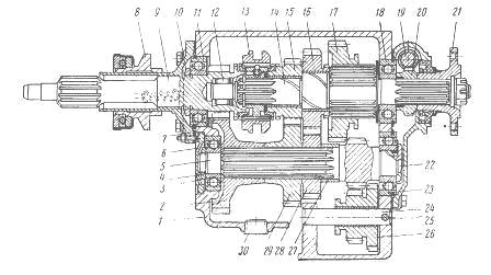
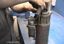
Transfer case assembly is done upside-down. These steps are repeated when working with other types of this car brand (including when repairing the UAZ Hunter gearbox). Install the fastener bracket to the frame. They put the transfer case on the parking brake drum and, holding the gear, lower it into place through the power take-off hatch.
Before this, place a lock washer from the intermediate shaft. Tighten the bolts and nuts, put on the cover with levers and check the operation of all gears. They change the release bearing, remove the levers, drag the entire unit under the car and hang it on a rope. Slide the release bearing assembly onto the box and reinforce the spring. Then insert the input shaft and clutch. This is done as follows:
Attach the oiler of the input shaft splines and the plug in place, put the speedometer drive, cardans, handbrake, covers in place. It is necessary to return the frame cross member to its place and fix the muffler bracket to the transfer case.
Adjustment and adjustment of the hand brake, oil change are performed. If the UAZ Hunter checkpoint is being repaired, you may need not only these actions, but also the adjustment of the rods. Screw the hatch on the floor, put the seats. This completes the repair of the UAZ 452 checkpoint on its own.
VIDEO
In order to properly repair the UAZ 452 gearbox on your own, you must strictly adhere to the sequence of actions described above. Difficulties in repairing other models of this brand may be caused by a different arrangement of the main parts of the machine, for example, rods. The oil change must be carried out in accordance with the technical requirements for this type of vehicle.
Do-it-yourself UAZ 469 checkpoint repair is a feasible task for a person who wants to save money. For other owners of UAZs (for example, UAZ loaf), all of the above can be taken into account and the UAZ gearbox can be repaired, taking into account some difference in details and the location of the rods.
The original article is on the site
Thanks to Alexander Dorokhov for sending me a lot of pictures of his box. Using these pictures as an example, I wrote this article.
This photo shows the cover with the shift forks. Visually, I didn't notice any wear on the forks! But be sure to move your hands forks. If they start to dangle on the rods, then it is necessary to unscrew the wire fixing them and tighten the bolts more tightly! So that visually they look great.
Now looking inside the box. One can only breathe.Here you don't even need a dipstick to see how much the second gear gear is worn out by the end of the output shaft in the area of the coupling teeth. Ideally should be 0.2mm. On the one who worked, of course, a little more. But here you can clearly see that the gap is at least 3.5mm. Such a gear is only ejected. Because her coupling teeth will only grasp halfway. Compare the length of the teeth and the width of the backlash yourself.
When the input shaft is removed, inspect it. The synchronizer is no longer good for anything, since its guide teeth are clogged to dullness. The clutch teeth have already done a good job. From the bottom of the teeth, uniform strips of working are clearly visible. But from above, on the other hand, rust is clearly visible on the far half of the tooth. This suggests that the gear clutch, when the gas was released, became sideways or was squeezed out. So that the input shaft is ejected together with the synchronizer.
We take out the synchronizer sleeve with the hub. Visually. The 4th gear teeth at the clutch look great. Unfortunately, their lateral wear from the teeth of the input shaft is not visible?
I wonder if the retaining ring came out by itself? If so, then the retaining groove on the output shaft broke into a cone and the ring squeezed out of it under load. So you have to go to the turner and he will neatly straighten this red-hot groove with a very strong cutter. Behind the ring you can see a spacer sleeve or washer, whichever you want. It will be necessary to put a new bearing on the shaft at the turner, put the retaining ring back in the groove, and the turner will immediately grind you a new spacer washer. The washer must be so thick that it fits between the bearing and the retaining ring with a slight interference or no more than 0.1 mm in the red. Although it is possible the store sells new circlips and spacer sleeves of different thicknesses. In any case, for a land Rover, this is how it is done. But I hope the retaining ring has been removed.
Here, too, I see a kind of wear on the walls. If yes! That means you need to put a new lock washer of greater thickness. But, if the synchronizer hub also dangles on the shaft splines. It's best to change the shaft too! Although the splines look neat and there are no signs of wear. Most likely the shaft is in good condition.
Addition to the written:
The clutch and teeth facing the 3rd or 4th gear looks good. The edges of the teeth are intact. I do not observe oblique wear. But if the gears change, then the clutch automatically changes together with the hub. Although I would put this part together with the hub, just in case, in stock. And if the money is really not enough, then I would put it. If everything is correctly adjusted, nothing will dangle and the transmission has not been knocked out before. I don't see any crime. The main thing is that the hub fits snugly on the shaft.
The same goes for the hub.
The replacement synchronizer has blunt edges of the teeth.In this case, they will not slide to the side when the clutch teeth go through them, respectively, the gear lever will engage the gear with some difficulty.
The gear of the third gear has teeth clogged to a bluntness, and traces of chips are also visible. It will be difficult to turn on the third gear and even then every other time. She's not a tenant! Replacement only. The former owner obviously did not bother himself to wait until the synchronizers equalize the rotation speeds of the shafts. Moreover, Nigrol contributes to this.
And this is how she looks from behind. The spacer washer which stands behind is strongly worn out. It is necessary to buy a new washer, preferably fitting it in size. As a last resort, carve a new one out of bronze. On my Lada there is a bronze one. The main thing is that the gearwheel of the 3rd gear wobbled on the shaft no more than 0.2mm. And the copper bushing began to crumble. This means that the gear was simply dangling on the shaft. But she has a tolerance of 0.06 mm.
Now comes the tricky part. Yes, you can measure the inner diameter of the gear with an internal gauge or a dijetal caliper. Then measure the shaft neck, subtract one from the other and get the result. Unfortunately, this measuring tool is more expensive than a new shaft, and much more! Therefore, I can offer only two options.
1) The bushing on the new gear is still sized and you can hardly change anything here.
2) Now the way to check the runout of the shafts in the bushings. On fingers. And in the literal sense of the word. The human hand begins to feel the beating of parts in the region of 0.1 mm. Well, if you already feel the beating with a clear thud. This means that the beating is already in the region of 0.2mm. and more.
But the most important thing here is not the beating of the gear on the shaft, but how great is the walk of the gear on the shaft.
The gear should walk as little as possible from the 3rd-4th gear clutch and to the stop end on the shaft. Ideally 0.08. 0.2mm.
And the second gear is out of competition. It has developed to such an extent that the development has consumed the sharp edges of the coupling teeth. And this is about a millimeter. It means that the gear shifted on the secondary shaft at least 3.5 mm (second photo) with a tolerance of 0.2 mm. Such a must to the museum!
The teeth on the gear of the first gear are also clogged, so that the second gear will turn on will be very problematic.
The intermediate shaft gear had not beaten teeth and not beaten splines. As a rule, this is always the case. If something has not damaged the teeth of the intermediate shaft, then on the shaft, as a rule, only the bearings are changed. The exception is heavily damaged reverse gear teeth.
The teeth on the reverse gear are jammed. Quite a common defect. It also needs to be replaced, since the wear goes to the taper, the gear may start knocking out after some time. Take a closer look at the larger gear - you can see better from below.
The axle on which the reverse gear rotates looks good. I really don't remember ever changing it.
But the bearing needs to be changed since it is already producing. Roller bearings have the main feature: if the roller fell out of the cage, then the bearing has worn out itself.
Judging by the photos. The croutons were removed from the synchronizer clutch. Nothing surprising. With such a large backlash of the gears (along the shafts), the clutch crackers of the 3rd and 4th gears began to crawl out behind the synchronizer clutch when the gears were turned on. After that, they began to bulge outward under the influence of a spring, and as a result, it was impossible to turn off the gear. Precisely, so that this does not happen, I try to choose all the backlash on the shafts of the box and the inclusion forks when repairing.
Verdict. In the box, you need to change the gear 1,2,3, gears. Also replace the input shaft, all bearings, reverse gear. Not strictly necessary, but requires a hub and both synchronizers. If the new gears dangle on the old shaft more than 0.15mm.(The hand perfectly feels the knock above 0.1 mm.) This means that the secondary shaft should also be replaced.
Dismantling the gearshift mechanism SEQUENCING
Use a narrow slotted screwdriver to knock out the plugs of the gear shift rods.
Using the "17" key, unscrew the plug-plug of the retainer socket.
Using pliers, remove the safety wire of the bolts securing the forks to the rods ...
... and turn off the three bolts with a 10 key.
We knock out the fork rod of the 1st-2nd gear with a beard together with the plug.
We take out the plug and stem.
The blocker pin is located in the middle rod.
... take out the ball with a spring.
Using the "10" key, unscrew the three bolts securing the fuse cover.
We take out the ball with a spring (fuse holder).
Sinking the ball with a slotted screwdriver, insert the stem into the hole in the cover.
We put a fork on the stem, tapping on the end of the stem with a soft metal hammer, ...
... and fix it with a locking bolt, aligning the holes in the stem and forks.
Install the plunger into the channel between the reverse gear fork and the III – IV gears.
Orient the oil deflector washer with a protrusion to the inner ring of the bearing.
ATTENTION The lever travel when engaging the first gear in a gearbox with synchronizers only in III-IV gears is 2.5 times greater than when engaging the second gear. Failure to engage the first gear causes rapid wear and destruction of the gears.
Yesterday there was such a situation: when the car was moving, there was a crackling and all transmissions stopped working. That is, when you turn on any gear and try to get under way, there is a crunch of gears, and the car does not move. Few people undertake to make these machines, and those who do it have a queue. I'll have to do it myself.
Now I will unscrew the cardan and remove the gearbox. I will try to repair it myself. Unscrewed the box mounting bolts: on one side 2 bolts; on the other side 2 bolts. Put down the pallet. Now I will try to shoot it. So she sagged. That's it, the box is removed. Now I will pull it out and examine it.
I took off the box, now I will disconnect it from the distributor. And immediately that catches the eye - this backlash, the backlash of the input shaft. It still remains a mystery to me how I will put it in its place, but time will tell. I disconnected the box from the distributor, and the second thing that caught my eye was that this nut was unscrewed. And it looks like we have a left-hand thread.
He unscrewed the cover, unscrewed the flange mounting bolts. Now let's see what's inside. I don't see anything dramatic yet. Now I'll see, if anything, I'll tell you. Apparently, this was the problem. This block of gears, this shaft is all shaking, dangling. And here it squeezed out the lid that needs to be screwed on.
Apparently, the problem is in this bearing of the gear block, because the entire shaft sometimes does not mesh, because it dangles. And the synchronizer has practically no teeth.I have a friend, a specialist in VAZ nearby, I will now consult with him and continue the repair.
I consulted with a specialist, they said that both bearings of the intermediate shaft and the bearing of the input shaft are being replaced. They told the ground synchronizer not to touch it, to leave it that way, because there are no rusks or balls. It will work fine. It is also necessary to change the oil sump washer.
I went to the store and bought bearings: 50 208 with a groove on the input shaft; 50 306 to the intermediate shaft. I still need a 305th open bearing without a groove, but there was no open one, I bought a closed one. Then I will remove these rubber things - it will be open. Also, sealant, gaskets for the box, oil squeegees and bolts for the universal joint.
Now we will disassemble the box. To remove the intermediate shaft, these gears must be removed. To do this, I unscrewed this bolt. It must be unscrewed. Now I will knock out the axle. All knocked out.
Now we will knock out the intermediate shaft itself. To do this, we need to unscrew this nut. And you will have to hit the bearing from the other side so that it falls out here. Now let's see how it goes. It was not possible to unscrew this cover, because it was squeezed out, and it did not go along the thread. I just broke it. I don’t know if there are such on sale or not, it is aluminum. Look what happened to the bearing there - practically nothing remained of it.
Now we need to press out the input shaft. Here on the gear there is a place where there are no teeth. It must be placed so that it does not interfere with the exit, so that the teeth do not cling to this gear. We twist, set, now we will press out. I found such an iron screwdriver, now I will put it. This input shaft came out very easily.
Let's go further. We pulled out the primary shaft, now we proceed to the secondary shaft. It is necessary to unscrew these bolts, remove this lock washer, and hit the bearing there so that the bearing comes out. I have already unscrewed these plates, which held the bearing in the groove. Now I remove the lock washer, then remove the lock washer. Now you can hit the bearing to make it come out. Now I will press out the bearing with hammer blows. The bearing needs to be pulled out of here, I'll try now. After removing the bearing and removing (inaudible 09:35) washers, I pull out the output shaft.
To remove the intermediate shaft, you need to unscrew this nut and drive it in there. Now let's try how it will be. I unscrewed the countershaft nut, there was a retainer from the bearing, and now we will pull out the gears. He understands everything here and so he should get out. Putting it together so as not to forget how they stood. Now I will wash, clean and start replacing parts and assembling the box. The box has been disassembled, now I will clean this centuries-old dirt with a scraper. Then I'll try, I have a cutter, you can also use a torch, I'll burn it all to keep it clean. Only then will I collect everything.
We install the intermediate shaft. First we put on the ring, then the small gear, then this one will go, the smaller one. Then we put the big one. Only we will insert all this inside, so we will analyze everything again.
Now we will press in bearing 50 306. We press it in on this side, go to the other side. Now we press in the bearing on the other side. We install the secondary shaft. We stuck the rollers on the grease, now we will insert them into the secondary shaft. That's it, there is nothing interesting here yet. Now we will collect everything, connect it to the distributor. The most interesting thing will begin when we put it in place.
Shock! In UAZ "loaf" invested 2 Llamas! What came of it
To insert the box into the distributor, you need to remove the hatch on the distributor and adjust the gears with your hands. It should line up with the output shaft. Using all kinds of pads, I set up the box like this. Now I will try to push it there. I do the work alone, I don't know if it will work out or not. Until the bottom can not put the box, I stuck it in there, but I have not yet hit the clutch.When I was redoing the floors in the loaf, they all rotted away, I foresaw such a hatch, it is held on by bolts. Now I will try to lift it with ropes from here and insert it.
Also look who is going to alter the body of the loaf, I have such a table. I have it that opens on bearings, and there is access to the rear of the engine. Now I will try to lift the box from here. Everything, as we can see, the box went into its mountings. Luke helped, but only two holes would be enough to stretch the rope. That is, I stretched the rope, tied it in a knot, began to twist it with a crowbar, and the box began to rise. I hope I did everything right. Everything, we collect further.
Having twisted a few turns, I lifted the box to the end, and now you can easily tighten the fasteners of the box pillows. So the hatch passed the test - a necessary thing. That's it, finished the work.
It took me 1,500 rubles for the material: for all the gaskets, oil, bearings. Last time I repaired a box in a car service, the first gear took off, they took 10,000 rubles. Today I had to do it myself, but I saved it.
UAZ-469 belongs to the number of cargo-and-passenger vehicles, which are distinguished by an increased level of cross-country ability. The car was produced by the Ulyanovsk Automobile Plant. In addition to UAZ-469, the car plant presented such models as UAZ 452 (loaf), UAZ Patriot.
On the UAZ 469, the gearbox is mechanical, designed for 4-speed. In this case, the 4-speed gearbox is equipped with synchronizers. They are needed to implement speed equalization. There are shafts, while the input shaft is based on two bearings. The intermediate shaft drive gears are helical. To accommodate the occurrence of radial and axial loads during movement, the rear shaft support includes a double-row angular contact ball bearing. Such a checkpoint allows the vehicle to move in reverse. The vehicle is equipped with a transfer case. Transfer case UAZ 469 includes drive axle shafts, gears, which have a long working life.
The advantage of a manual transmission is that it is designed for a long service life. The car, which has off-road qualities and is equipped with a manual transmission, is excellent for cross-country operation.
The vehicle must be diagnosed if its handling has deteriorated. In parallel with this, squeaks can be heard when changing gears. Also, it is necessary to check the state of the box if the transmissions are activated spontaneously. In some cases, it is necessary to replace bearings and gears in order to solve the problem with the occurrence of noise. If the gear shift is tight, the synchronizers are checked. The main reason why there is a need to replace the component parts of the box on an SUV is their natural wear and tear.
One of the signs that the transfer case should be checked is if the grip of the wheels with the road has deteriorated, and noise from its side has begun to build up. Improper use of the vehicle leads to the repair of the gearbox on the UAZ 469. In particular, it is necessary to replace the transmission oil in a timely manner.
Another problem that a UAZ driver may encounter is oil leakage from the gearbox. This manifestation is the result of an increased oil level in the gearbox. Also, if water gets into the system while filling the box with new fuel, the motorist will soon encounter the problem of fluid leakage from the gearbox. However, not only the use of low-quality oil can be the reason that a leak will be noted, since there may be a crack on the crankcase or in the cover of the UAZ 469 gearbox.
VIDEO
Thus, the high-speed box of the UAZ 469 car includes many working units that ensure the optimal functioning of the automotive system. Given this, the owner of the vehicle must subject the car to regular maintenance. This will reduce the risk of premature repair of the UAZ 469 gearbox.
What kind of locksmith tools are needed to repair a gearbox? To carry out repairs, you should acquire a whole repair kit. In particular, you will need open-end wrenches, socket wrenches, a hammer, screwdrivers, and a mounting spade.
It should be noted the large weight of the box, all due to the fact that the device has a message with a dispenser. With this in mind, dismantling the box should not be done alone.
How to remove the box? To start the procedure for withdrawing the checkpoint, follow these steps:
UAZ stands on the observation hole.
The transmission oil is drained (this will slightly lighten the weight of the box).
The seats are dismantled in the cabin.
The clutch release fork, frame, cardan shaft, speedometer shaft, clutch pan, muffler adjacent to the distributor must be removed. The curtain must be removed.
The transfer case must be disconnected from the main gearbox. As a rule, the distributor is wrapped with rope and hung.
All consumable parts (bolts, nuts, etc.) are unscrewed.
Since the UAZ gearbox is fixed on the fasteners, they must be unscrewed and the box can be removed from the slots.
VIDEO
The assembly of the UAZ gearbox occurs in the reverse order.
When the removed box is disassembled, all component parts must be checked for integrity. Deformed elements must be replaced.
If you more and more often have to hold the gear lever on the move, if the transfer case levers have been tied with strings for a long time :), if a discordant concert begins under you even on the rear axle, then it's time. It's time to remove the box and figure out how this collection of gears and bearings works.
I warn you right away - I'm not going to argue with the authors of books on UAZ, this article is only an addition to the books, taking into account the fact that you do not have a service station, a lift, three mechanics and the like.
See what kind of gearbox you have. If you are unfamiliar with the concept of "double release with re-throttle", all gears, both "up" and "down", are easily shifted, and the lever travels the same distance when engaging first gear as when engaging third - you have a fully synchronized gearbox. Everything that will be written further about the gearbox does not apply to you. However, the transfer cases are the same, and some of this article may still be useful to you. For off-road conditions, it is preferable to have a gearbox with synchronizers only in third-fourth gears, the so-called. "Old model".
Having decided on the type of your box, we will prepare the tool. For complete disassembly and assembly of the "old-style" gearbox and transfer case without any special tweaks, you need the following tool:
I use red “ABRO” for the gaskets. Domestic white is suitable only for water supply, and even then not everywhere.
I use "Litol" as the cheapest grease.
In UAZ vehicles, the gearbox and transfer case are interlocked into one unit, which is very correct. But it's very hard (80 kg). Therefore, it is quite difficult to remove this weighty unit alone (and this is what happens most often). The photo shows how I get out of the situation - with the help of the manual winch "Lika-2". But I have a roll cage that I grab onto it. Having once forgotten the winch, I got out of the situation with the help of an ordinary crowbar and rope. But I will not undertake to put the box into place alone without a winch.
So let's get started. We put the car on a flat surface, considering that it will have to be rolled half a meter back and forth.Drain the oil - the gearbox and transfer case have separate drain and filler plugs, although the volume is common.
While the oil is draining, remove the front seats. Then we unscrew and remove the two halves of the hatch in the floor. We turn away and remove the speedometer drive further away.
The oil is just glass, we wrap it in the place of the cork. Unscrew the frame cross member, which runs directly under the parking brake drum. Unscrew the cardans from the transfer case flanges. It is more convenient to unscrew the front cardan if the front axle clutches are disengaged. If your cardan shafts have weak spline nuts, it is better to remove the cardan shafts completely from sin, in general, it is enough to tie them to the frame so that they do not interfere. It is much more convenient to unscrew the rear cardan from the top, from the hatch, here the car will have to roll slightly forward and backward. We unscrew the muffler from the transfer case and loosen the clamp on the muffler itself, otherwise it will interfere.
We wrap the box with the distributor with rope and hang it up. Unscrew and remove the bolts of the pillows, unscrew the nuts securing the box to the bell. Do this gradually, the nuts on the left side will completely unscrew only when the box has already partially moved away from the bell. Help yourself with a montage. In this case, it is better to prop the engine with a jack, otherwise it will remain on two supports and the “rear” part will go down - it will interfere. When the box finally hangs, gently lower it down. It is better to change the studs in the bell - they experience heavy loads, and 50/50 that the thread on them is damaged. If the car is on the ground, the levers must be removed for ease of pulling it out from under the car. When removing the gear lever, the cover must be held - there is a spring under it.
neat oblique blows on the shaft we press out the bearing of the input shaft. The main thing is not to rush and beat in a circle, so as not to distort the bearing and spoil the landing one. In the photo, the shaft, which I have already taken out three times, which was before me - I do not know. As you can see, it is hot and does not suffer from blows. If the bearing of the input shaft is worn out, knock down and install a new one. He suffers perhaps the most, so 90% will have to change him. These bearings come with a closed and open cage, I did not understand the difference - it is still under the cover.
Inside the input shaft lives roller bearing without clip. Most likely, it crumbled during disassembly. Collect it. If the last roller gets up easily, you need to change it. With the new set of rollers, the latter can only be inserted with great difficulty and "along". It even seemed to me that they slipped the wrong one :).
First, you need to loosen the nuts of the flanges and shafts of the transfer case - for this, we insert bolts of suitable diameter into the two holes of the flange and hold them with a mounting. The shaft nuts are hidden under the covers, it is imperative to unscrew them - the shafts can be removed with the nuts, but then it is very difficult to unscrew them. Unscrewing the flanges, remove the handbrake (at the same time, you can check its performance and change the pads). The soured working cylinder is disassembled and soaked in diesel fuel, checked. There are no spare parts for the brake - either pads or all assemblies.
We remove the covers with oil seals and change the oil seals (unless they are completely new), not forgetting to fill the free space with "Litol". Unscrew the bolt by 10 and take out the speedometer drive. Unscrew the breather and replace it with a new one (100% soured). Better yet, a pipe to the salon. Unscrew the stopper for the guide forks.
Now you can “halve” the transfer case - Remove all retaining rings from the bearings, unscrew all the bolts around the perimeter and remove the large-sized cover. If necessary, we change the roller bearing in this cover, the inner race is pressed onto the shaft. There are two bearings on the rear axle shaft, the second one must be inspected.
The razdatka is assembled in the reverse order. It is necessary to carefully inspect the flanges and replace at the slightest sign of wear on the splines, it progresses very quickly. Wear on the forks is also unacceptable. Do not forget to core the nuts.
Let me extract one detail in your story about the repair of the RK, namely: when you change the roller bearing on the intermediate shaft, you need to knock out the plug in the RK housing that closes it, because the bearing race is pressed in 3 mm from the outer edge of the housing (you cannot catch this without removing the plug). The plug itself is put into place already on the fully assembled RK (so that you can check the bearing preload). Before installing the plug, straighten on the plate, then a thin layer of sealant is applied to the edges of the hole in the RK housing under the plug and the plug is set in place using a mandrel (instead of it, you can use a piece of pipe 6-8 mm smaller in diameter, i.e. a tight fit is achieved due to the uniform indentation of the middle).
We glue the gaskets between the box and the distributor on the sealant. We put in place the bracket for fastening to the frame. We put the transfer case on the hand brake drum, and holding the gear in the transfer case through the “power take-off hatch” we lower the box into place, not forgetting to put the same “intermediate shaft thrust washer”. We take care of our fingers. We tighten two bolts and two nuts, put on covers with levers and check the operation of all gearboxes and handouts. We are glad that it turned out.
We change the release bearing for a pre-welded in nigrol. We remove the levers, drag the unit under the car and hang it on a rope. We put the clutch release assembly on the box, put the spring. Now the most difficult moment is to insert the input shaft into the clutch. Slightly moving the box up and down, turning the engine with a jack and turning the engine by the flywheel, sooner or later we put the box in place.Do not put the box right next to it - first, on the left, insert the growers with nuts into the slot. We pull the unit to the engine, fasten it to the pillows. We install in place the clutch fork and the oiler of the input shaft splines. We put in place the speedometer drive, covers with handles, handbrake, cardan shafts. Please note - in stores, disposable gimbal bolts are often sold. The normal bolt is hardened, with an “X” on the head. The letter "Ч" on the head means the manufacturing plant and does not serve as a guarantee of strength. We put in place the cross member of the frame, we fasten the bracket of the muffler to the distributor. Setting up the handbrake.
Video (click to play).
Fill up with oil, put the hatch in place, the seats and go to check the results of a well-spent weekend 🙂

