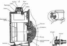
In Niva 21213 and 21214 cars, a mixed-type excitation starter is installed, with an electromagnetic-type traction relay and two independent windings. Four poles are fixed in the housing, one of which is connected in parallel, and the rest - in series. The casing with the cover is pulled together with a pair of bolts. Inside there is an anchor with a collector (the latter is of end type). The anchor rotates on sintered metal bushings pressed into the covers.
Despite the apparent structural complexity, starter repair is available even for beginners. The main thing is to have the necessary tools at hand, diagnose the malfunction in a timely manner and follow the manufacturer's instructions. Below we will consider what starter malfunctions exist, and how to fix the problems.
In the cases described above, the defective element is replaced or repaired, the contacts are cleaned.
2. When the key is switched in the ignition lock, the relay works, but the starter does not turn (hot or cold). Causes:
Depending on the malfunction, the defective part is replaced or repaired, the contacts are cleaned or the short circuit is eliminated.
3. As soon as voltage is applied to the starter, the relay is activated multiple times with subsequent disconnection. The engine does not turn (the problem manifests itself on hot or cold).
4. After energizing, the starter armature rotates, but the engine flywheel does not. Causes:
5. A strange sound appears when scrolling the anchor:
6. The gear hangs in fixing with the flywheel:
To check the VAZ-2121 relay, apply a voltage of 12 Volts to the relay output, and apply "-" to the case. Connect the resistance meter to the terminals. If the relay is intact, then the armature extends the overrunning clutch, and the contacts are closed. If a part is found to be defective, replace it.
Blow out the cover and the Niva brush holder with air. timely diagnose malfunction and correct it correctly.
VIDEO
1. Clean all parts of the starter.
2. Check the condition of the stator winding. To do this, turn on the test lamp in the 220 V AC circuit and connect the wire to one of the terminals of the stator winding, close the other end of the circuit to the case. If the lamp is on, then the insulation of the winding is damaged. Replace winding or stator. Check the second winding in the same way (see note).
The stator windings can be checked with a megger. Connect one contact to the terminal and the other to the stator housing. The resistance of the windings must be at least 10 kOhm. If it is less, replace the stator.
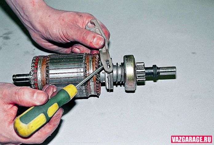
3. Examine the anchor. If the collector is dirty or has risks, scratches, etc., sand it with fine glass cloth. If there is significant roughness in the collector or if there are mica protrusions between the plates, grind the collector on a lathe and then grind it with fine glass cloth. The runout of the core relative to the shaft journals should not exceed 0.08 mm. If the runout is greater, replace the armature.
4. If you find a yellow coating from the bearing on the armature shaft, remove it with a fine sandpaper, otherwise it will cause the pinion to jam on the shaft. If there are scuff marks, nicks on the surfaces of the journals and splines of the shaft, replace the armature.
The armature windings can be checked with a megger. Connect one of its contacts to the collector, the other to the armature core. The resistance of the windings must be at least 10 kOhm.Replace the armature with less resistance.
5. Check the reliability of soldering the leads of the armature winding to the collector plates. Inspect the winding at the ends of the armature: the diameter of the winding should be less than the iron package of the armature. If the diameter is larger, replace the anchor.
6. Check the condition of the armature winding with a test lamp in the AC 220V circuit. Connect the wires to the collector plate and the armature core. If the lamp lights up, then there is a short circuit of the armature winding or collector plate to ground. In this case, the anchor must be replaced (see note).
9. If the drive parts are badly worn or damaged, replace the drive. If nicks are found on the lead-in part of the gear teeth, grind them with a fine-grained small-diameter emery wheel.
10. Inspect the manifold side starter cover and intermediate support. If cracks appear on these parts, replace them. Also inspect the bushings in the cover and in the support in which the armature shaft rotates. If severe wear or mechanical damage is found, replace the cover or support with defective bushings.
11. Inspect the bushing pressed into the clutch housing. If the bushing is worn or has scuffs, pits, etc., replace the bushing.
12. Brushes worn down to a height of less than 12 mm must be replaced.
13. Check the movement of the brushes in the holders: the brushes should move easily, without jamming. Check that the brush holders are securely fastened: they must be firmly attached.
14. Holders of insulated brushes must not have a short to ground. Check this with a test lamp.
15. Check the force of the springs pressing the brushes with a dynamometer. To do this, insert the armature into the cover from the drive side, install the housing and the brush holder. Insert the brushes into the brush holders. At the moment of separation of the spring from the brush, the force should be in the range of 9.0-11.0 N (0.9-1.1 kgf).
16. Check the resistance of the traction relay windings with an ohmmeter. The resistance of the retraction winding should be within 0.52–0.59 Ohm (red), and the holding one - 0.725–0.795 Ohm (yellow) at an ambient temperature of +15 to +25 ° С. The traction relay armature must move freely in the housing, without jamming.
Simultaneously with checking the resistance of the winding, check whether the contact plate closes the contact bolts of the traction relay. If the ohmmeter shows “∞”, then either there is an open in the winding, or the plate does not close the contact bolts. In both cases, the traction relay must be replaced.
1 - contact plate 2 - rectangular slip ring heads
17. Inspect the contact bolts. Sand the burnt bolt heads with fine sandpaper. If the heads are heavily burned out, you can turn the bolts 180 ° so that they are pressed against the contact plate with the unburned side. If the surface of the contact plate is badly worn, then it can be turned with the other side towards the contact bolts.
We clean the starter from dirt and set it in a vice.
Using the "13" wrench, unscrew the nut of the lower output of the traction relay.
Using the "8" head, we unscrew the two bolts of the traction relay ...
We remove the anchor of the traction relay.
Using the "10" wrench, unscrew the nuts of the tie rods.
We remove the stator together with the anchor from the cover studs.
Use a Phillips screwdriver to unscrew the two screws ...
We remove the central gear from the armature shaft ...
We take out three planetary gears.
Use a soft metal drift to knock out the drive shaft ...
... and remove it assembled with the drive shaft support and the lever.
Remove the gasket.
We install the drive shaft on a wooden stand.
... and, hitting the key with a hammer, press the restraining ring.
Starter 35.3708 is a four-brush DC motor with mixed excitation and an electromagnetic two-winding traction relay.
Four poles with excitation windings are fixed in the starter housing with screws: three series (serial) and one shunt (parallel). The body together with the covers are tightened with two bolts.
Anchor - with end manifold.The rear end of the armature shaft rotates in a sintered bushing pressed into the cover from the collector side, and the front end in a bushing pressed into the cover from the drive side. A freewheel clutch (freewheel clutch) with a drive gear is installed on the drive shaft. It transmits torque in only one direction - from the starter to the engine, decoupling them after starting the engine. This is to protect the starter armature from overspeed damage. The traction relay is used to enter the drive gear into engagement with the gear ring of the flywheel of the engine crankshaft and turn on the power to the starter motor. When the ignition key is turned to the "starter" position, voltage is supplied through an additional relay of type 113.3747-10 to both windings of the traction relay (retraction and holding). After the contacts of the traction relay are closed, the retraction winding is disconnected. The operating voltage of the traction relay should be no more than 9 V at (20 ± 5) ° С. If not, there is a fault in the relay or actuator. Serviceability of the drive is determined by inspection after disassembling the starter. The defective relay is replaced.
We look at the removal of the starter in the article - "Replacing the VAZ-21213 starter".
Starter technical characteristics 35.3708
In Niva 21213 and 21214 cars, a mixed-type excitation starter is installed, with an electromagnetic-type traction relay and two independent windings. Four poles are fixed in the housing, one of which is connected in parallel, and the rest - in series. The casing with the cover is pulled together with a pair of bolts. Inside there is an anchor with a collector (the latter is of end type). The anchor rotates on sintered metal bushings pressed into the covers.
Despite the apparent structural complexity, starter repair is available even for beginners. The main thing is to have the necessary tools at hand, diagnose the malfunction in a timely manner and follow the manufacturer's instructions. Below we will consider what starter malfunctions exist, and how to fix the problems.
During operation, the following problems are possible: 1. After moving the key in the ignition lock, the Niva car does not start, the starter does not turn. Causes of the problem:
The power supply of the machine is discharged.
The outputs on the battery or the terminals of the connected wires are oxidized.
Terminals are loose.
Turn-to-turn short circuit or damage to the traction relay winding.
The turning on starter relay is out of order or there is a break in the supply wire of the device.
Lack of closure between the "thirtieth" and "fiftieth" contact.
In the cases described above, the defective element is replaced or repaired, the contacts are cleaned.
2. When the key is switched in the ignition lock, the relay works, but the starter does not turn (hot or cold). Causes:
The battery is discharged or out of order.
Loosened fasteners of the cable ends connecting the motor with the body part.
Oxidized "plus" and (or) "minus" on the power supply, poor broach.
The collector is burnt out, the brushes are worn out.
The "plus" terminal of the brush holder was on the ground.
An open circuit occurs in the armature and (or) stator windings.
Depending on the malfunction, the defective part is replaced or repaired, the contacts are cleaned or the short circuit is eliminated.
3. As soon as voltage is applied to the starter, the relay is activated multiple times with subsequent disconnection. The engine does not turn (the problem manifests itself on hot or cold).
With this they read Where are the relays in the cornfield
Short circuit or open circuit of the relay coil.
Battery discharge.
Reducing the voltage on the relay contacts (occurs when the wires are oxidized).
4. After energizing, the starter armature rotates, but the engine flywheel does not. Causes:
The lever for engaging the clutch liner is out of order.
Slipping clutch.
5. A strange sound appears when scrolling the anchor:
The starter fasteners are loose or the device is attached at an angle.
The integrity of the flywheel gears or drive gear is damaged.
Bearing bushings worn out.
The starter fasteners are loose.
6. The gear hangs in fixing with the flywheel:
Lever, traction relay, or spline clutch seized.
The ignition switch is broken (at the junction of the contacts).
The traction relay springs are loose or out of order.
VIDEO Regardless of whether the engine is turning or not, each of the above cases requires repair or replacement of damaged components. How to do this work, we will consider below.
Algorithm of actions: Use a key to "thirteen" to loosen the fasteners of the conductor connected to the traction relay. Discard the tip.
To check the VAZ-2121 relay, apply a voltage of 12 Volts to the relay output, and apply "-" to the case. Connect the resistance meter to the terminals. If the relay is intact, then the armature extends the overrunning clutch, and the contacts are closed. If a part is found to be defective, replace it.
To remove the traction relay, use a slotted screwdriver to remove the three screws.
Pull the spring rod out of the device casing, and install the new traction relay according to the reverse algorithm.
If the problem persists, continue with the repair:
Take a Phillips screwdriver and twist off a couple of screws, then remove the cover.
To check the integrity of the brushes, twist the fixing screw of the contact conductor, and then use a screwdriver to squeeze the spring. Next, it remains to remove the brush.
In the same way, take out the other three brushes and inspect them. If at least one of the brushes is up to 1.2 centimeters high, then it must be replaced (further use of the part is not recommended).
With this read Where is the turn signal relay, how to replace it
Connect a multimeter to the starter windings (one at a time) and check for a short circuit. The task is to make sure that there is no short circuit between the turns and to the case.
Using a screwdriver, lift the locking ring, remove the washer from the shaft and use a ten wrench to twist a pair of tie bolts.
Separate the starter elements and remove the insulating tubes.
Inspect the appearance of the windings and the collector. Remove traces of the collector's burning with a sandpaper. If this part is badly worn out or charred, then the repair is useless - the device is changing. Remove seizures with a fine-grained emery cloth, and then polish the product.
Use a multimeter to check the armature for short circuit. Change the node if you find a problem.
Get the rubber seal out of the drive cover and remove the washer to adjust the armature.
Remove the link pin cotter pin and select the latter. Next, you need to remove the armature together with the drive.
Pry up the screwdriver drive arm and remove it.
Check the car's gear - it should scroll easily left and right. Also inspect for nicks and chips. If the gear is worn out or the clutch is out of order, then it is useless to make repairs - change the assembly.
Support the shaft against a piece of wood and knock out the stop ring.
Use a screwdriver to pry on the ring and remove it.
Remove the stop ring and freewheel with gear.
Collect the starter by the reverse algorithm.
Blow out the cover and the Niva brush holder with air. Lubricate the eyeliner ring with a lubricant (Litol is suitable). Treat the splines of the shaft and bushing with engine oil.
Correct repair of the starter is a guarantee of a clear start of the engine, both hot and cold. The main thing is to diagnose the malfunction in a timely manner and correct it correctly.
There will also be proposed solutions to the problems encountered in the field on the channel. If you are interested, subscribe.
Disconnect the negative wire from the battery. Dismantle the air filter housing (see Removing the air filter housing).
Remove the front support bracket for attaching the intake pipe to the engine support bracket, disconnect the starter heat shield from the exhaust manifold and from the engine support bracket (see Replacing the gasket of the intake pipe and exhaust manifold of an injection engine).
1. Using the "13" key, unscrew the bolt of the upper fastening of the starter to the clutch housing (this bolt also attaches the rear support bracket of the intake pipe to the clutch housing).Similarly, we unscrew the bolts of the middle and lower starter mountings, move the starter forward.
2. Disconnect the traction relay control wire.
3. Using the "13" head, unscrew the nut of the "positive" starter wire
4. Remove the wire. In photo 1, for clarity, the receiver is removed, and in photo 2, 3, 4 - the inlet pipe and exhaust manifold.
5. Retract the starter along the cylinder block back
Removing the starter from a carburetor engine is easier due to the lack of intake pipe support brackets. Install the starter in reverse order
The starter on the Niva has to be changed quite rarely, but if you have a need for this, then the instructions below will be very useful. First, it's worth considering the necessary list of tools with which it will be very simple to do all this and will not take much time.
Key for 13
Ratchet with small extension
Head 10
First of all, we open the hood of the car and disconnect all power wires from the starter structure. To do this, you need to unscrew the 10 nuts with the head that secure the terminals. A normal wrench will not crawl in there, so a ratchet with a head and extension would be ideal. We feel the terminal nuts with our hand and, using the ratchet handle, turn them off in turn.
To show everything clearly, look at the photo below, the key will be inserted just under the Niva exhaust manifold:
And after that, you can freely disconnect the power wires, which are no longer attached to anything:
Next, we take the key 13, it is more convenient to use the cap, and unscrew the 2 bolts securing the starter housing to the engine. But there may be three of them, personally, in my example, there were only 2.
And then you can shoot it to the right, as shown clearly in the photo below:
And turning it a little to the side, we take it out without any problems up:
As you saw for yourself, there is nothing complicated in this repair, the main thing is that all the necessary tools are at hand and then any work with your Niva will be done quickly and without unnecessary nerves.
The VAZ 2121 starter is installed in the reverse order of removal. If necessary, we can replace it with a new part.
VIDEO
our group VK Music track provided by
A car starter can be a surprise. An inoperative starter is a common problem when there is no starting. The video shows a common reason when the starter does not turn. Video author: Valery Chkalov. ________________________________________________________________ Visual and detailed recommendations for self-service maintenance and repair of cars. With an equipped place, a set of tools and hands, a car enthusiast can perform most of the maintenance operations on his car. Car repair is a certain order of not complicated operations. The channel contains technically competent service reviews from various authors. The channel is not planning commercial monetization. The main task of the collection is to promote the ARBIX trademark. ARBIX is an online car platform, a guide to car services. The site is a marketplace with simple and convenient mechanisms. The system offers advanced communication schemes and foresees the future of the automotive industry.
In this video I will tell you how easy and simple it is to remove the pallet on the Niva without removing the entire engine itself! It turned out to be not easy, but we did it all the same! I told everything in the video! Links: I'm on DRIVE2 Vkontakte Instagram Regarding advertising, you can contact the site in Vkontakte as well as by mail -
Deprivation of all-wheel drive fields. The video describes all the nuances of this alteration. everyone does it naturally at their own peril and risk 🙂 The pros and cons of this shift. Why is it needed and how I did it in this video. Join the Vkontakte Facebook group Publish your videos, links, schemes, ideas, discuss interesting topics with friends. Support and share with your friends! I will be very grateful. How to transform four-wheel drive in mono-wheel drive and why? Deprivation of NIVA the full of drive. The video explains all the nuances of the alteration, making each course at your own risk 🙂 Pros and cons of this change. Why do you need and how I did it in this video. If you have any more questions or suggestions, write in the comments under this video, I will try to help. Or write me an email in the "About the channel" section on the main page of the channel, we can discuss specific issues and advise on other related topics. If you still have questions or suggestions, please write in the comments under this video, I will try to help you. Or write me an email in the “Channel Info” link on the main page, we can discuss private matters and to consult on other related topics.
VAZ-2121, 2131, LADA 4x4 Urban Years of production: 1977 - present LADA 4 × 4 "Urban" 2014 - present
In the video Starter repair classic. you will take away possible breakdowns, and their elimination .. as well as in the video Starter repair classic. you take away how and with what you can check the starter and repair the starter .. This starter is for vaz 2101, vaz 2102, vaz 2103, vaz 2104, vaz 2105, vaz 2106, vaz 2107, and it can also stand on vaz 2108. See video Starter repair classic. and take it all away yourself.
Often, owners of a VAZ 2121 or 2131 SUV face problems associated with starting the engine. For example, when turning the ignition key, the starter does not turn. Consider the possible problems of the Niva 4x4 starter and how to solve them.
The starter relay is located under the additional fuse box next to the ignition relay. On Niva 21214, the starter relay is attached to the injection relay bracket.
1 - starter; 2 - storage battery (joint stock bank); 3 - generator; 4 - starter activation relay; 5 - ignition switch
Starter connection diagram: When the starter is turned on, the voltage from the battery through the auxiliary relay (No. 4 type 113.3747-10) is supplied to the windings of the starter retractor relay (retractor II and holding I). After the contacts of this relay are closed, the retractor winding is disconnected.
Initially, the blog was dedicated exclusively to my NIVA (VAZ 21213 (1994 release). Now I am collecting interesting facts, manuals, pictures, videos and other useful things about NIVA.
You are absolutely right, you need to buy a new one, not play constructor 🙂
By the way, the father-in-law says that the parts are out of standard, so we changed the retractor again, but this time to the old one:
It is even worse when the retractor sticks. It happens regularly with me.
Starter repair for VAZ 21213 NIVA:
At one point, the car stopped starting.
The problem was with the starter, and specifically with its design.
Apparently, sometime before me, the starter already had to be sorted out, because it was not assembled correctly.
I came to this conclusion after seeing an extraneous detail.
An extra element, a washer, was installed on the rotor shaft, next to the brass bushing.
From the factory, according to the technological drawing, it should not be there.
This washer, over time, cut a slot on the rotor shaft (in the last photo it is clearly visible ) and when starting the engine, at a certain moment it got there, thereby stopping the electric motor, stopped further starting the engine.
International Niva Club
Message Mikhail Belaya Niva "Dec 20, 2014 11:53 pm
Message Maxim_agent 23 Dec 2014 09:14
Message cheloboz »07 Jan 2015, 17:37
The car refused to start, and at first it started up as usual, but when starting off with the back, the sole of the boot was in the snow and slipped off the clutch. stalled and did not start. They took me by dragging, drove to the house.
Today I took off the starter (gear), I think the retracting one is guilty. We'll fix the damned piece of iron.
The question is - what current is consumed by the starter retractor relay?
Message al-awast »07 Jan 2015, 17:43
Message cheloboz »07 Jan 2015, 17:48
2004 is the year of birth of my tram.
I entered this information into my profile.
Message al-awast »07 Jan 2015, 19:29
Here is a copied answer from the adjacent forum
“On a 2002 car, two relays are screwed on the left below the small fuse box. One of them is the right one. If the car is an injection machine (in the profile after 2131 it would not hurt to add the letter i or k for certainty), then these two are screwed in the same place to the relay bracket of the engine control system, but you still need to look at the two separate wires and the color of the wires that match them (look on the diagram). "
Message cheloboz »07 Jan 2015, 19:59
Thanks for the link and comment, added the letter “i”
In my tram there is definitely no starter relay, the place where it should have stood and felt and looked, but there is only an ignition relay and four more relays.
I gutted Google and found the solenoid relay currents:
From this I conclude that it is imperative to install a starter relay. Otherwise, I'll ditch the ignition and whatever else along the way.
————
Conclusions:
90 Niva VAZ 21213 starter device repair
Starter
Starter 35.3708
1 - drive gear;
The starter type 35.3708 is a direct current electric motor with a mixed
Four poles 18 with field windings are fixed in the housing 17, three of which
Starter wiring diagram
1 - starter;
When the starter is turned on, the voltage from the battery through the auxiliary
Video (click to play).
Starter technical characteristics

