We disassemble the steering mechanism during its repair.
Remove the steering rod support.
We unscrew the nut, striking the beard (right-hand thread) ...
Use a screwdriver to wring out the two retainers of the sleeve located inside the pipe ...
Remove the two rubber rings from the bushing (arrows show the bushing retainers).
If it is necessary to replace the nut, open it with pliers to remove the circlip ...
We take out the rubber plug from the adjusting nut of the rail stop.
Unscrew the stop nut with a special “24” wrench with an external octagonal head.
We take out the stop spring.
… Remove the O-ring.
By hitting the crankcase on a wooden block, we knock out the rail stop.
… Remove the insert from the stop.
Remove the rubber ring from the crankcase that seals the hole for the steering gear on the bulkhead.
Remove the boot from the pinion shaft.
Remove the cage with thrust bearing rollers.
Remove the cover O-ring.
We take out the rack from the crankcase.
We press out the pinion shaft by clamping the shaft in a vice with soft metal jaws and pressing the crankcase upwards with a mounting blade.
We take out the gear shaft with the bearing from the crankcase.
... and remove the bushing retaining ring.
We take out the pinion shaft sleeve assembly with a base plate.
If it is necessary to replace the needle bearing with a drill with a diameter of 4 mm, we drill two diametrically located holes in the crankcase so that they go to the end of the outer ring of the needle bearing.
Using a puller, we press the ball bearing of the pinion shaft with the inner ring of the roller thrust bearing.
Using a puller, we press the inner ring of the needle bearing from the shaft.
Use a screwdriver to pry on and remove the gear shaft oil seal from the crankcase cover.
... with a scraper, remove the extruded metal in four places and take out the ring.
… And press on the crankcase with light hammer blows through a block of wood.
We press the gear shaft oil seal into the cover through the mandrel or the head flush with the end face of the cover.
After tightening the pipe fastening nut, tighten the nut.
We turn the gear shaft so that the flat on it is located on the right side. We move the rail so that the steering rod support, installed on the rail, is located in the middle of the pipe groove. Insert the rail stop, the stop spring and tighten the stop nut. It is recommended to replace the stop nut with a new one.
... so that the foot rests against the end surface 1 of the stop, and does not fall into its hole 2 (for clarity, it is shown on the dismantled stop).
Each car owner of Lada Kalina, sooner or later, will face the problem of failure and repair of the steering rack. Of course, experts and auto mechanics recommend changing this element, but not everyone can afford to buy this element, so repair is a way out.
VIDEO
The video material will tell you how to repair the steering rack, give basic recommendations and assembly features.
Steering rack repair kit
Before proceeding with the repair of an element, it is necessary to accurately determine that it is the steering rack that has failed on the car. For this, there are indirect and direct signs that will indicate the detail. Of course, it is best to carry out diagnostics at a specialized car service, but you can try with your own hands, for example, tighten the steering rack, but here you need to proceed carefully.
So, let's consider the main signs of a malfunction of the steering rack:
When you turn the steering wheel, a knock appears under the hood.
Longitudinal rudder play.
Increased steering effort.
Oil spots under the machine.
Steering wheel sticking when cornering.
All these signs are direct in the event of a malfunction of the steering rack, which will be the first bells that the element needs to be diagnosed and repaired.
General view of the steering
There are not many reasons for the failure of the steering rack, but you need to know them. Timely maintenance, as well as diagnostics of the unit can extend the life of the element.
Consider the main causes of steering rack malfunctions:
Deterioration of the elements that make up the rail.
Accident damage when a wheel is struck.
Other reasons that led to the fact that the rake began to leak.
All these reasons become the reason for repairing the steering assembly.
In order to repair the steering rack, you need to know its design and the elements that make up it. Consider the node design diagram:
Steering rack diagram
Steering rack details: 1 - rack bushing ring; 2 - support sleeve of the rail; 3 - steering gear housing; 4 - roller bearing; 5 - drive gear; 6 - ball bearing; 7 - retaining ring; 8 - protective washer; 9 - a sealing ring; 10 - bearing nut; 11 - lock washer; 12 - anther; 13 - rail; 14 - protective cap; 15 - rail stop; 16 - sealing ring; 17 - retaining ring; 18 - stop nut; 19 - clamp; 20 - protective cover; 21 - inner tip of the steering rod; 22 - connecting plate; 23 - lock plate; 24 - bolt for fastening the rod to the rail; A - a mark on the boot; B - mark on the crankcase
For restoration work related to the steering rack, a repair kit is required. Usually, they cannot be found in specialized stores, and motorists, as a rule, go to the car market, where they can purchase a set of spare parts. For the price it is much cheaper than buying a new rail.
The steering rack repair kit can be purchased individually or as an assembly.
Repair kit for Ricardo steering rack
2110-3403090-11 is the catalog number of the complete steering gear repair kit for Lada Kalina. Separately, bushings and plastic inserts can be purchased, but it is not recommended, since the quality of the products may be different, and, accordingly, the wear on the left and right sides may differ.
When all the materials for repairing the steering rack have been collected and purchased, you can proceed directly to the repair operations.
Before starting, the entire steering rack must be cleaned. This can be done manually, but it is best to use a steam mechanism under pressure, which will qualitatively remove dirt and dust from all elements without damaging the parts.
Now, we proceed to the sequential operations for repairing the steering rack:
We substitute the brake shoes under the rear wheels and remove the handbrake.
Putting the shoes under the wheels
Removing the coupling fixing bolt
We take out the cotter pins with pliers
Removing the tie rod ends with a hammer and crowbar
Disconnecting the EUR connector from the on-board network
Removing the steering rack mounts
Dismantle the steering rack through the wheel arch
We cut off the clamps of the anther using nippers
Dismantle the rack housing cover
We diagnose the condition of all products.The plastic and rubber parts will have to be replaced and a new boot and bearings are recommended.
Before assembly, it is necessary to clean all the parts, lubricate the rack and pinion shaft with lithol or other similar grease.
We start assembling:
Installing new bearings
We bring the marks on the crankcase and rail so that the steering wheel is level
We put on a new boot on the rail
Many car manufacturers do not recommend repairing the steering rack, but at the same time they produce repair kits. So, in the repair manual for AvtoVAZ, it is clearly stated that the failure of the VAZ 1117-1119 steering rack must be replaced with a new one.
Also, motorists and car steering repair technicians recommend, after repairing the steering rack, after 1000-1500 km of run, tighten the threaded connections that could loosen due to vibration.
Motorists recommend that maintenance of this unit should be carried out every 10,000 km. It includes a visual inspection for leaks, checking the condition of the anthers, and tightening the connections.
As experience shows, repairing the Lada Kalina steering rack with an electric power steering can really be done with your own hands. Of course, this procedure will take a day, maybe two. The main thing is not to rush and choose all the quality and correct parts. It is recommended to install new bearings, because even if there is no play, it is not known after how long it may appear.
Removing the steering mechanism of the Lada Grant is necessary in the event of a breakdown of the steering mechanism, as a rule, plastic parts fail (wear out). As a result, the steering loses its “sharpness” of control, knocks are heard in the steering when driving over irregularities. Removal of the steering gear is carried out according to the following instructions.
The operations are shown on a VAZ 2110 car, the operation algorithm for the Lada Grant car is the same.
2. In the engine compartment, using a “13” key, unscrew the nuts securing the steering brackets to the front end of the body on the right ...
We disassemble the steering mechanism during its repair.
Remove the steering rod support.
We unscrew the nut, striking the beard (right-hand thread) ...
Use a screwdriver to wring out the two retainers of the sleeve located inside the pipe ...
Remove the two rubber rings from the bushing (arrows show the bushing retainers).
If it is necessary to replace the nut, open it with pliers to remove the circlip ...
We take out the rubber plug from the adjusting nut of the rail stop.
Unscrew the stop nut with a special “24” wrench with an external octagonal head.
We take out the stop spring.
… Remove the O-ring.
By hitting the crankcase on a wooden block, we knock out the rail stop.
… Remove the insert from the stop.
Remove the rubber ring from the crankcase that seals the hole for the steering gear on the bulkhead.
Remove the boot from the pinion shaft.
Remove the cage with thrust bearing rollers.
Remove the cover O-ring.
We take out the rack from the crankcase.
We press out the pinion shaft by clamping the shaft in a vice with soft metal jaws and pressing the crankcase upwards with a mounting blade.
We take out the gear shaft with the bearing from the crankcase.
... and remove the bushing retaining ring.
We take out the pinion shaft sleeve assembly with a base plate.
If it is necessary to replace the needle bearing with a drill with a diameter of 4 mm, we drill two diametrically located holes in the crankcase so that they go to the end of the outer ring of the needle bearing.
Using a puller, we press the ball bearing of the pinion shaft with the inner ring of the roller thrust bearing.
Using a puller, we press the inner ring of the needle bearing from the shaft.
Use a screwdriver to pry on and remove the gear shaft oil seal from the crankcase cover.
... with a scraper, remove the extruded metal in four places and take out the ring.
… And press on the crankcase with light hammer blows through a block of wood.
We press the gear shaft oil seal into the cover through the mandrel or the head flush with the end face of the cover.
After tightening the pipe fastening nut, tighten the nut.
Scheme for monitoring the clearance in the engagement of the rack and pinion shaft:
We turn the gear shaft so that the flat on it is located on the right side. We move the rail so that the steering rod support, installed on the rail, is located in the middle of the pipe groove. Insert the rail stop, the stop spring and tighten the stop nut. It is recommended to replace the stop nut with a new one.
... so that the foot rests against the end surface 1 of the stop, and does not fall into its hole 2 (for clarity, it is shown on the dismantled stop).
VIDEO
Video about how I repair steering racks and cardan shafts Kalina, Grant, Priora. After a lot of hard work with the steering in my car, I found a way to make this unit more reliable and durable. Now I help others to get rid of knocking at the steering wheel for a long time.
In the video, only my own experience is not claiming to be true. It's just that it's convenient for me to repair the steering that way.
I'm on LKF />
VIDEO
VIDEO
Remove the front wheels and battery from the vehicle;
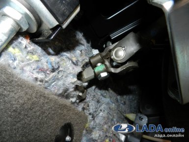
Inside the Lada Granta cabin there is a terminal connection of the steering system with an intermediate shaft. It is necessary to unscrew the bolt that is responsible for this connection. The steering wheel must be in the state in which it holds the wheels of the Lada Grant in a straight position.
Disconnect the tie rods from the steering arm and steering system.
There is a gap in the wheel arches through which you can unscrew the nuts that strengthen the steering gear.
Then it is necessary to completely remove the fastening clamp and pull out the entire mechanism.
The plastic clamps must be cut off and the steering protection cap removed.
In the future, it is necessary to remove the pads of the clamps, the mounts of the anthers and the anthers themselves.
Now you can assemble the Lada Grant mechanism. The position of the staff should be medium. If the gear rotates, it means that it is necessary to move the rack in any direction. Next, it is necessary to adjust the final position of the river so that the marks of the anther and crankcase coincide.
The last thing that requires repairing the steering rack is wheel alignment.
Video (click to play).
VIDEO
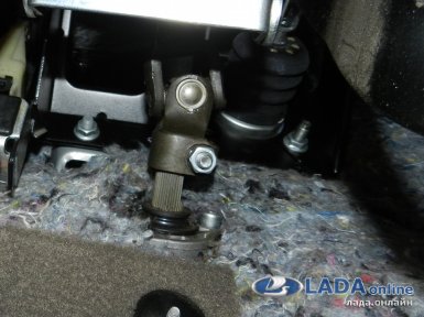 fastening the steering shaft Lada Granta, viburnum, prior

