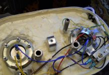
Details: vitek vt 1194 bk DIY repair from a real master for the site my.housecope.com.
VT-1187-88.rar 56.73 KB Downloaded: 7643 times
I need a circuit thermos kettle Thermopot Lentel E208
Thermopot Lentel E208 I need a schematic diagram
Vitek VT-1187Gy another scheme is not suitable. The board is written model rsp11_01 therefore the microcircuit series HT46R47 is not suitable
0_86663_213df648_XXXL.rar 245.41 KB Downloaded: 3805 times
Uncle YuraWhy not bother with the topic? Vitek VT-1187Gy does not include the pump? Defective where is it? Checked the electric motor is working well
Please help me determine what kind of microcircuit in this circuit without designation, thanks in advance!
VT-1189 (38Y) -SCH.rar 63,27 KB Downloaded: 1871 times
1. Before creating a new theme
2. When creating a new topic
1. In the title of the topic, in the original font and in the given sequence, indicate the type of equipment, brand, model, and briefly the problem.
3. State the problem - a manifestation of a defect,
Banned
Posts: 104
Salomon_Z thank you so much. intact. apparently a smart guy by nature? but I'm not into a bastard, I write for the gifted. This is an electric kettle Thermopot VT-1189. MODEL BM_RSP22_01.
2008/09/01. The malfunction is as follows: After pouring cold water into it, boiling does not turn on, only the heating lamp blinks and the heating coil is turned on. After checking, I found out that this particular microcircuit does not work
For example, the VT-1191 thermo-pot (I think the circuitry is similar), if it was disconnected from the network and then turned on - when water is poured, the green heating LED flashes and the heating coil is turned on, to turn on the heating of the main coil, press the RE-BOILING button. This is by the way and is in the instructions. But when adding cold water IMMEDIATELY, the heating of the main spiral turns on, and the red and green LEDs are on.
| Video (click to play). |
Maybe someone knows a simpler way to turn off the fucking blocking of water filling. From the keypad to the control board (at the bottom of the thermopot) there is a loop of 7 wires - lilac, yellow, black, blue, brown, gray and white. I think somehow it is necessary to directly finish. need a diagram or practical thoughts. THANKS in advance friends.
Vanvanych. it doesn't matter, you can press the boil button right away, but when adding cold water, the temperature sensor should work and the boiling spiral will turn on, but alas, this does not happen. The sensor and the key assembled on the Q2 transistor works, the signal goes to the microcircuit, but there is no signal output from the microcircuit
Vanvanych. but how does the blocking work, I have no one on my teapot
Vanvanych. I understand, I'll look and let you know
Vanvanych. look at the diagram above, I posted it, there the control comes from this microcircuit, the Q3 key to the engine is turned on by feeding a logical one,
in my version, all control is tied to this microcircuit. You can globally change the pump switching circuit, for this you need to separately feed a logical one to the base of the transistor Q3
Electric kettles - thermoses, or thermopots, serve regularly for 2 - 3 years, then usually fail. The main reasons for this: they stop boiling water, do not pour boiling water, and because of the flow of water. There are many materials on the Internet about the repair of thermocouples, but there are almost no schemes. The article briefly describes the models of thermopots, the diagrams of which are copied from the products, the malfunctions of which the author encountered during the repair. The article provides examples of circuit solutions used in most models of modern thermopots, despite the large number of clones produced by various companies.
In the given diagrams, the designations of most of the parts correspond to those indicated on the boards. For different models of thermocouples, the secondary power supply circuits and control units are very different. All thermo pots have a stainless steel boiling tank. In its lower part there are fixed thermoelectric heaters, heating elements, usually two of them, for boiling and heating water, in this case they are in one block, which has three outputs.A thermal switch for a temperature of 88 - 96 degrees C or a thermal sensor is fixed at the bottom of the tank, giving a signal to turn off the heating element of the boiler when the required water temperature is reached. On the side wall of the tank, a thermal switch connected in series for a temperature of 102 - 110 degrees C and a fuse FU for 125 degrees C / 10A, placed in a silicone tube, are fixed. They cut off the power supply to the thermopot when the temperature of the boiling vessel rises due to lack of water or in the event of a short circuit. To supply hot water in thermopots, the same type of DC motors for a voltage of 12 V, with a centrifugal pump, are used.
Most of the parts for thermal pots are located on two boards. The control board, on which the control buttons and LEDs are located, is located in the upper part of the case. The main board, on which most of the power connectors, control units, relays, sources and secondary voltage stabilizers are located, is located in the lower part of the case under a container for boiling water. Both boards are interconnected with wire harnesses with connectors.
The diagram of the Elenberg TH-6030 thermo-pot, [1] is shown in Fig. 1. Earlier, in 2014, the author posted it on the go-radio site, so a link to this site is given. The TN-6030 circuit is quite simple and completely analog. Constantly through the heating element for heating water EK1 and the diode VD9, a pulsating current flows in only one direction, therefore the resistance of this heating element is two times less than that of a similar heating element of the same power in other models, where it is powered by alternating current. When the electric motor is turned on, a constant pulsating current of a different polarity begins to flow through it and the VD10 diode, up to 150 mA, and an alternating current flows through the heating element EK1. Automatic switching on and off of the heating element for boiling water EK2 is performed by the SF1 thermal switch. Forced switching on of the heating element EK2 for up to 2 minutes is made by contacts K1.1 of relay K1. For transistors VT1 - VT2 of the control stage of relay K1, a constant voltage of 14 V, stabilized by the chain R3 and VD6, is supplied from the diode bridge VD1 - VD4. A frequent malfunction of this model of a thermopot is the burnout of the contacts of the SF1 thermal switch, because the entire current of the heating element EK2 passes through it. Replacing the thermal switch is not difficult, you need to unscrew two screws on the flange, and rearrange the two power connectors. Detailed videos of this replacement are available on the Internet.
Another malfunction, poor operation of the hot water supply pump. Its cause is an increase in the friction of the rotor axis of an electric motor operating at an elevated temperature due to a deterioration in the quality of the lubricant. The magnetic clutch of the pump consists of a magnetic disk, put on the rotor shaft of the electric motor and the pump impeller, put on the axle shaft in the pump casing cover. A magnetic disk is also fixed at the base of the impeller. An airtight gasket is installed between the two magnetic disks. Rice. 2.
The author lubricated the bearing points of the rotor at the ends of the electric motor housing with ordinary spindle oil. Helped for a couple of months. It is difficult to get to the front point of support, you had to disassemble the pump and pour oil under the magnetic disk, and turn it with your finger, at this moment the electric motor is in a vertical position so that the oil flows into the right place. The remaining oil is drained over the edge. It is not necessary to remove the disc from the rotor axis, a couple of removals and it will not stay on the rotor axis. It is easier to immediately replace the motor with the pump.
Water leaks in thermopots are rare, usually due to mechanical damage. Once the reason for the appearance of water under the kettle was an inconspicuous crack in the upper part of the plastic case, under the lid, running along the rim of the container for boiling water. Steam penetrated this gap, which then condensed on the inner surface of the walls of the case, the plastic crumbled along the crack. That kettle was beyond repair.
Photo of the VT-1188 main board. Rice. 4.
The diagram of the VT-1191 thermo-pot is shown in Fig. 5. The secondary voltage source for control units is pulsed, made on a VIPer 12A microcircuit according to a transformerless circuit. A constant voltage of 18 V at its output is filtered by capacitors EL3, C3 and a choke L2, then the zener diode ZD2 is lowered to 12 V. The control circuit works on the ic1 processor, there is no marking on its case, there is only a label indicating the model of the thermo-pot. A voltage of 5 V to ic1 is supplied from a regulator on transistor Q4 and a zener diode ZD3. There are two heating elements in the VT-1191 thermo-pot: EK1 for boiling and EK2 for heating water. Contacts K1,1 of relay K1 alternately connect the conclusions of one of them to the network, depending on the voltage at pin No. 5 of ic1, which, through the CN1 connector, LED HL2 and R7, goes to the base of the transistor Q1. A small base current of transistor Q2 flows through the SF2 thermal switch, so SF2 is connected to the board and pin no. 4 of ic1 with a low current connector. The electric motor is turned on by the Q3 transistor when a "+" appears on pin # 3 of ic1. The malfunction of the thermo-pot manifested itself in the fact that it did not boil or pour water, only the green indicator HL3 was on. The cause of the breakdown was the failure of the ic1 processor.
There are many tips for repairing thermo pots, but I will add two more:
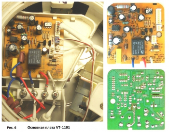
1) Take pictures of the entire process of disassembling and repairing the kettle. This will then facilitate its subsequent assembly and especially, the installation of power connectors. (Fig. 6).
2) If the housings of the low-current connectors installed on the boards are even slightly loose in their places, these housings must be glued to the board and the contacts must be soldered. Violation of the connector contacts after repair and assembly of the thermal pot can lead to new malfunctions.
The electric kettle has stopped heating the water. At the same time, the indication and the pump motor are working, there are no wire breaks or damage to the connectors, the heater is in good order. Inspection of the printed circuit board showed that the foil around the hole for the output of the middle (movable) contact of the JH3001 electromagnetic relay (Fig. 1, pin 5) in the power supply circuit of the electric heater was burnt out. Pin 5 itself also burned out to the plastic base of the relay case. The relay was removed from the board and, since there was no replacement for it anyway, it was disassembled.
Rice. 1. Electromagnetic relay JH3001
For this, in the lower part of the case, at a distance of 3.4 mm from its base, a saw was carefully made with a hacksaw along the entire perimeter. The overheated and overdried plastic of the case broke off immediately, at the same time a small part of the base of the case, which covered the remnants of the burned out terminal 5, broke off at the same time. The latter was on a flat bronze spring of the relay's movable contact, it was made of its lateral protrusion folded in half (Fig. 2, a). The bottom part of the spring, bent at right angles, is attached under the base of the relay coil. A flat lead in a round hole does not solder well, especially in auto soldering mode. Over the three years of operation of the kettle, the soldering gradually collapsed and the output burned out. When trying to unbend the remainder of pin 5, it broke off the spring along the fold line. The relay did not have any other malfunctions: the winding was intact, the contacts were serviceable and switched.
To restore the output, the area in the lower part of the bronze spring was tinned (Fig. 2, b). A piece of single-core tinned wire with a diameter of 0.75 and a length of 30 mm, bent at a right angle, was soldered to it. Its part, placed inside the relay case, was previously flattened with pliers. When the relay was installed in place, the new pin 5 easily entered the hole intended for it, after which it was bent onto the previously tinned section of the printed conductor adjacent to the burned-out one, cut off “in place” and soldered to it. To avoid unsoldering the output from the spring of the movable contact, the soldering point was held with tweezers to remove heat.
To glue the sawn-off part of the case to the base of the relay, “Modelist” glue was used; In the end, all loose connectors were soldered on the board of the electric kettle and fixed with glue, and it was installed in its place. The electric kettle has been working reliably for over a year.
- Panshin Andrey / 10/12/2018 - 15:37
Roman and Alexey, thank you. Yours faithfully, Panshin Andrey. - Alexey / 08/04/2018 - 10:02
Krasava, painted everything, painted. Understandable and accessible. Huge respect to you - Roman / 01/02/2018 - 17:30
Thanks a lot. The same problem and your solution. Issue price 0 rubles.
You can leave your comment, opinion or question on the above material:
To read the instructions, select the file in the list that you want to download, click on the “Download” button and you will be redirected to the page where you will need to enter the code from the picture. If the answer is correct, a button will appear in place of the picture to receive the file.
If there is a “View” button in the field with the file, it means that you can view the instruction online without having to download it to your computer.
If your material is not complete or you need additional information on this device, for example, a driver, additional files such as firmware or firmware, then you can ask a question to the moderators and members of our community, who will try to promptly respond to your question.
You can also view the instructions on your Android device.
The electric kettle has become an indispensable attribute of any kitchen and is the bestseller in comparison with other household appliances. This device is widely used both at home, in the kitchen and in the office. But unfortunately, like any electrical appliance, the kettle breaks down after a while. Since the price of this water heater is not too high, it is easier to buy a new one than to repair it. But if you consider yourself a home craftsman, or an apparatus for boiling water is dear to you as a memory, you can try to repair the electric kettle with your own hands.
An electric kettle works on a fairly simple principle, regardless of whether it is an expensive model or a budget one. At the bottom of the device there is a heating element connected to a thermostat, consisting of bimetallic plate... A tubular heater, when an electric current is applied to it, heats the liquid to a boil. When steam is formed during the boiling process, it passes through a special channel to the thermostat, as a result of which the latter turns off the power supply.
If you look at the operation diagram of the device, you will notice that it works on the principle of an iron, and does not differ in the complexity of its design. But before you repair the electric kettle, there are always difficulties when disassembling the case, since the latches (holding the handle) are located differently for different models of units, in addition, the fastening screws can be with a head for a special screwdriver.
An electric kettle is a simple device that contains few elements that can fail. But still, there are common problems, among which the following can be distinguished:
- slow heating of the liquid;
- the device shuts down prematurely;
- the kettle does not turn off;
- the device does not turn on;
- burnout of the heating element;
- water leaks from the housing.
If you notice that the kettle does not heat up the water quickly, then pay attention to the condition of the heating element. Thick layer of limescale on it, formed due to insufficiently good maintenance of the unit, has poor thermal conductivity, which is why it takes more time to heat the water. If the scale is not removed, the heating element may burn out.
In addition, the entire contact group of the device suffers from overheating, as a result of which the contacts melt or burn out.
To get rid of limescale, you can use a regular citric acidsold in stores.It is enough to pour 1-2 bags of citric acid (20 grams each) into the tank, bring it to a boil and leave the heated solution in the container for 30 minutes. After that, the container must be thoroughly rinsed with running water to remove scale residues. If necessary, the procedure can be repeated.
This behavior of an electric water heater is explained by the fact that the device may turn off due to scale formed on the heating element. Since the heating element has a fuse against overheating, it works and breaks the electrical network. To eliminate the malfunction, it is necessary to descale the heaters.
During the boiling of water in the vessel of the apparatus, the steam must be collected under the lid and directed through a special channel to the thermostat. If the lid is not closed tightly, then this does not happen, and the electrical appliance will work without shutting down. If everything is in order with the lid, check that the steam hole on the side of the handle is not clogged with limescale. In the case when everything is in order with the hole, it can be assumed that the kettle does not turn off due to breakdown of the thermostat.
The thermostat at the electric kettle is located at the bottom of the case, and in order to get to it for replacement, you will have to disassemble the device completely.
As an example, a conventional budget device was taken, which does not differ in design from more expensive models - an electric kettle Vitek, Tefal, Polaris, Scarlett and others. By the way, in this model, as in the Vitek VT-7009 (TR), the container is made of heat resistant glass... So, let's analyze the unit according to the following algorithm.
-
Repairing a kettle should start with disconnecting it from the mains... Next, remove the device from the stand (base) and unscrew all the screws on its bottom panel.
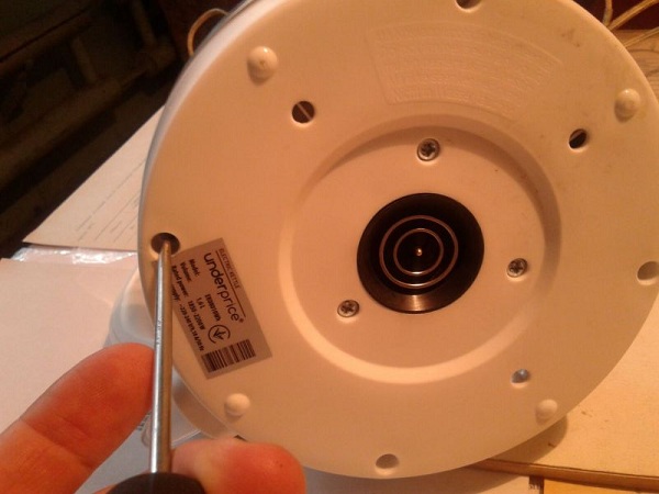
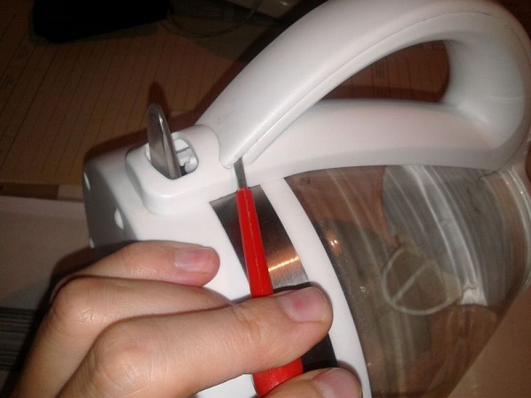
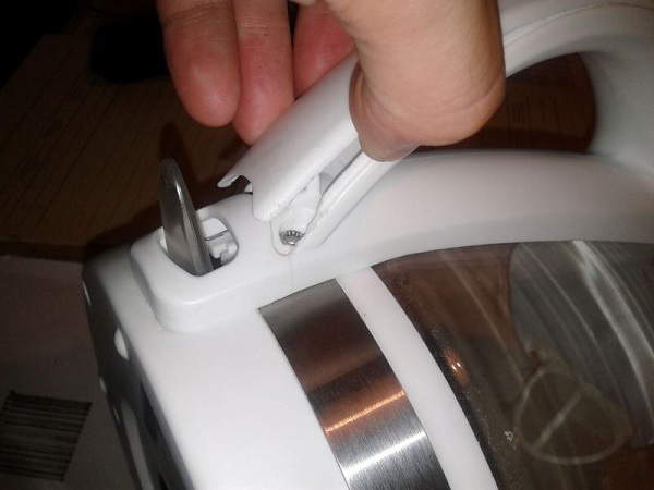
After that, it is necessary to pry off the plastic cover on the handle with special care using a thin screwdriver. This should be done carefully because in different models of devices the latches can be located in different places, and it is easy to break them.
Removing the trim reveals the mounting screws. They also need to be removed.
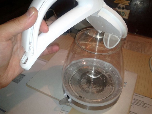
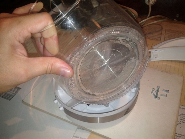
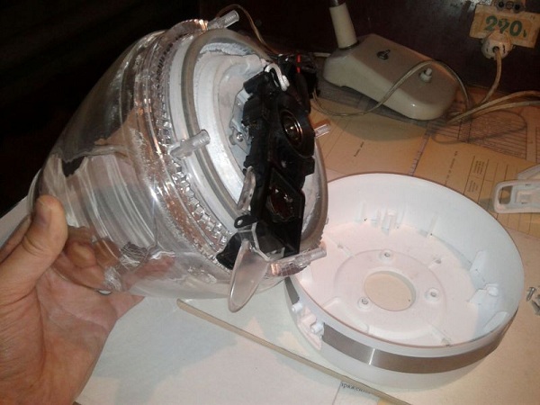
At the bottom of the case, you will see all the main elements of the device: contact group, thermal relay and heating element.
But how to disassemble a Bosch kettle if, when you unscrew all the screws on the bottom, it cannot be removed? Those who disassembled such a device faced difficulties, which often ended in a breakdown of the device. Since the process is quite complicated to describe, it is better to watch a video on this topic.
There are various reasons why your boil machine will not turn on.
- Faulty electrical cord and plug... To do this, you need to “ring out” the cord with the tester, touching the probes to the contacts of the plug and the contacts on the base (base). If a break is found, replace the cord with a new one.
- Poor contact in the stand (base). From prolonged work, the contacts can burn, due to which their conductivity is disturbed. If fumes have formed on the contacts, they can be cleaned using fine sandpaper. But in the case when they have melted, they will need to be completely replaced.
- Internal switch defective in the device. Since the switch has to experience quite large loads (from 1500 to 2000 W), its contacts can melt over time. This may cause the device to not work. The switch is located at the bottom of the handle, and in case of malfunction it looks as shown in the figure below.
In this case, the button must be replaced.But there is a malfunction of the button, in which you can fix the kettle with your own hands without replacing it. If you look at the button from the side, you can see 2 contacts, which in the “on” position close. If on them carbon deposits form, the device will not turn on.
To remove carbon deposits, you can use fine sandpaper, a nail file, or a thin file. To make it more convenient to do the stripping, you will need a small "revision" of the button, namely, removing the sides with a pair of nippers.
Another reason that the device does not want to work can be called malfunction of the mechanical power button... This breakdown is most often found in the Tefal vitesse model, since plastic slats are built into the handle of the electrical appliance, which transmit the translational movement from the outer button to the inner one located at the bottom of the unit.
After this part breaks, it becomes impossible to turn on the Tefal kettle. To understand in more detail how to repair an item that has broken, you can watch a video that describes one original way to fix a defect.
When repairing electric kettles, both old and newer, the most common breakdown is heating element burnout. The problem with heating elements arises, first of all, due to their overheating due to untimely descaling.
Before you repair a kettle with a disc heater or a heating element in the form of a spiral, it is necessary to disassemble the unit as described above. After that, take a tester and connect the test leads of the device to the output contacts of the heater. If the light on the device lights up, or it emits a sound, then the heating element can be considered serviceable.
How to check the heating element if no measuring device? It turns out to be very simple. It is necessary to connect zero from the mains to one contact of the heater, and a phase to the other. Next, insert a 220 light bulb into the socket, from which 2 insulated wires are taken out. Touch one stripped end of the wire to one contact of the heater and the other to the opposite. If the light is on, then the heating element is working properly.
If it turns out that the disc heater has burned out, then it cannot be replaced, since it is one piece with the bottom of the electrical appliance, such as in the Scarlett kettle, or Vitek VT-7009 (TR). Therefore, you will have to buy a new unit. Only open-type heating elements can be replaced.
If you notice that water is flowing (leaking) from the reservoir of the device, then it is recommended to use such a device for a while, until scale forms in the microcracks, which can block the seepage of liquid. If this does not help, then you will have to buy a new "boiler" if the warranty period has expired.
Another reason that the reservoir is leaking may be loose connection of the electric heater with the device body (if the heating element is open). In this case, you can tighten the fasteners holding it. If this does not help, then you will have to remove the heating element and change the rubber gasket, which is worn out.
Thus, we can summarize: in some cases it is quite possible to repair the unit for boiling water on our own. But if you do not have enough certain skills in the repair of household appliances, then the best option would be to buy a new kettle. Repair in a service center, from a financial point of view, does not justify itself, and there is no guarantee that the breakdown will not happen again.
Objectively arguing, seeing the minimum price limit for the device of 1300 rubles (Eldorado), you consider repairing a thermo-pot with your own hands a thankless task. Products rarely break, new ones are provided with a guarantee (store, manufacturer). For those wishing to repair a thermo-pot with their own hands, those who are hunters, who make a living by repairing, suppliers will provide spare parts separately for various modifications of the device.
The metal body protecting the thermo-sweat should not be heated by water.A serviceable product is equipped with a pump controlled by a mechanical button (trivial pump), or an electric one. The thermo-pot modes function properly for any duration of operation. The listed signs characterize a properly working modern analogue of a samovar. Deviations indicate a breakdown of the thermopot. Even a sticky button.
The Vitek thermopot power supply board costs over 800 rubles. Textolite carries:
- transformer;
- diode bridge;
- several resistors, capacitors.
A typical getinax substrate is supplemented with a pair of active elements, mainly transistor switches. The new VT-1187 thermopot costs 2,000 rubles, the control and power boards — 1,500 rubles (a difference of 25%). A $ 30 pump will shake the will of an experienced repairman as strong as a rock - an economically unprofitable event. Do you still have a strong desire to repair a thermopot with your own hands? Let's start by examining the power cord.
The body of the thermo pot is fastened with several screws: unscrew the fasteners by first pulling out the plug from the socket. A block will be found inside, we begin with a visual inspection. Burned parts inside the thermopot accurately indicate the location of the breakdown. The cord is neatly separated, the tester is called by the tester (diode mode). The detected wire malfunction will not delay the repair of the thermopot.
A typical thermal pot holds two printed circuit boards:
Both the master will inspect, revealing the presence of swollen capacitors, burnt resistors, unusable fuses, broken tracks. Defective radioelements are replaced with new ones, soldering, contacts are restored by tinning.
The first study concerns the presence of fuses, the integrity of the elements. If the replacement fails, the new element burns out - the cause of the problem is the electronic filling. The thermo-pot is damaged by a short circuit (a sharp uncontrolled increase in current).
The resistor values are indicated by colored stripes. A common problem is to detect the beginning and end of the marking.
Hint: there are special sites containing tables of all kinds of resistance symbols. Get access to the resource by filling out the search engine line with the simple phrase "marking resistors online." The direction of the stripes is determined by the observed fact: a fixed set of colors meet from one edge.
It is easier to notice damaged electrolytic capacitors - the cylinders swell. Newbies looking for ways to fix a thermopot are interested in the appearance of a broken container. The answer will come automatically, only a faulty capacitor comes across. The appearance of the cylinder prompts the thought: the keg is 100% swollen. The sidewall especially protrudes (imported ones are cut crosswise).
It is more difficult to test with diodes, but the semiconductor burns less often (silicon keeps temperatures below 150 degrees Celsius). Solder the element, ring both sides. The arrow markings show the direction of flow of positive charges (lean against the positive lead of the tester).
The torn tracks of the board must be cleaned with sandpaper, peeling off the varnish on the metal. The shiny surface is tinned (soldering irons), butted, covered with solder. It will serve for decades. Mechatronics masters repair and work ...
The thermo-pot pump serves the purpose of supplying water through the faucet. Manual, electric modes are possible. The construction, formed by a few simple windings, will not present any mysteries to an experienced electrical engineer. In pairs, contacts are called, otherwise for the mentioned Vitek 1187 you will have to pay $ 30 looking for a new pump. It will be useful to check the pump removed from the thermo-pot for suitability by setting the required voltages to the control windings. Remove the required 12V from the batteries, car battery.
The desired voltage is provided by computer power supplies.
It is not recommended to try to replace flat sheets of metal equipped with terminals with homemade ones. The cost of heating elements on the shelves starts at $ 45.
Overheating protection is provided by bimetallic thermal switches. The characteristics of the thermo-pot are determined by the control part. Usually there are several thermal switches, one controls the water parameters, the second protects against the inclusion of an empty tank. In the latter case, the heating element acquires a temperature above 100 ºС and opens the power circuit.
The surfaces of the tank, thermoswitch flange are in contact. To improve the contact, a special paste is used, similar to the one covering the surface of a processor cooler of a personal computer.
The principle of operation of the sensitive element is as simple as possible. Having noted the fact that the controlled environment has reached a certain temperature, the contacts of the thermal switch open. The parameter value decreases (15 - 30 ºС) - conductivity is restored. The type of components is difficult to find, once reading the description of the thermal pot, the body of the part is marked accordingly. The latter will allow you to choose a suitable spare part.
More often, the manufacturer is not content with the given protection scheme, supplementing the equipment with thermal fuses: small cylindrical parts tightly pressed to the tank wall with strips (brackets), glued. Having fixed the achievement of the critical temperature by the metal container of the thermo-pot, the fuse blows out, further work is impossible without replacement. Therefore, it is necessary to carefully inspect the product for such damage.
The serviceability of the bimetallic contact (room temperature) is checked by dialing. Desolder the part before the procedure. Normal conditions leave the contacts short-circuited.
Most thermopots operate a hackneyed electrical circuit, allowing you to isolate typical symptoms of a malfunction for units:
- The device does not turn on, there are no signs of life. The serviceability of the power cord, fuses, thermal switches is checked.
- Water does not boil when pouring, the reboil button is operational. The bottom thermoswitch has broken.
- Reverse situation: the reboil button does not work. The elements of the electronic filling are to blame. You must trace the circuit from the power supply to circuit ground.
- There is no main heating, the order with the auxiliary one. The heating element has burned out, or the power supply circuit is broken.
- The water supply is lousy. Two options:
- An additional heating element has burned out, the situation is diagnosed by the absence of standby heating.
- The pump motor is defective.
To top it off, we want to familiarize the reader with the types of thermopots. Let's discuss the models that the search engine stubbornly hides, ignoring the obvious attractiveness of the product. The costs of SEO promotion unfairly distribute the search results.
Ceramic thermo pots in type (and material) differ little from a teapot made of baked clay. VC-3230 with a volume of 1.2 liters, traditional three temperature settings, a convenient stand that can accommodate a control panel. Why does the manufacturer use the services of potters when making a thermopot body? Environmental friendliness. A popular word today. Humanity knows no more harmless materials than shards of baked clay used for thousands of years.
Thermopots are designed for small gatherings. Water boils for a few seconds. A minute is enough, get 1 liter of boiling water. The option is ideal for housewives who have sat down to forget household chores.
The Japanese manufacturer Zojirushi will help those looking for an elite thermopot: it presents chic models with Teflon-coated heaters, microprocessor control. The kettle will delight the owner with the required water temperature, in the morning it will warm up the liter in advance, controlled by the timer command. The convenience of a thermopot is achieved by electronics, and a lot of energy is saved.
Termopot Delta is a representative of budget options. For $ 39, he will be happy to heat water, serve as a portable thermos.The model provides the global properties of the considered class of household appliances, including water dechlorination, three temperature modes, and a removable cover.
In the middle price segment, we will call the Hotter thermopot a typical representative. Covering the $ 80 niche, the models are perfect for offices, apartments.

